

By 1919, the standard British Army field gun was the QF 18-Pdr Gun Mk IV on a Mk IV carriage. Both were significantly different to that of the QF 18-Pdr Gun used at the start of WW1. The original Mk I gun was slung beneath the hydro-spring recoil system while the Mk IV gun was mounted above a new hydro-pneumatic recoil system. The original Mk I carriage used a pole trail that limited the maximum elevation angle to +16 degrees and the maximum range to 6,525 yd. In contrast, the Mk IV carriage used a box trail with a space between the arms for the gun to recoil up to a maximum elevation angle of +37.5 degrees. This increased the maximum range to 9,100 yd. The Mk I-IV carriages all provided up to 4.5 degrees of traverse to the left or right.
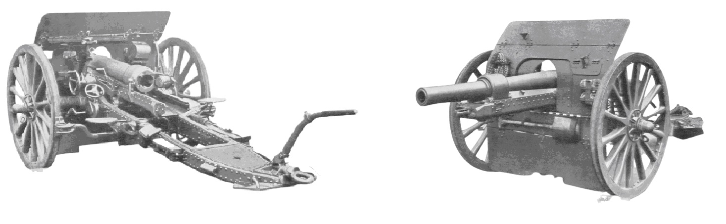
The Mk IV was followed by the Mk V carriage in 1923 that featured a split trail allowing up to 25 degrees of traverse to the left or right. However, in the 1930’s, the guns were converted to mechanised rather than horse towing and, to facilitate the high speeds involved, the original wooden wheels were replaced by pneumatic wheels. The converted guns in service at that time were designated the Mk IVP and Mk VP.
The QF 18-Pdr served alongside the QF 4.5-Inch Howitzer that, in contrast with the field gun, produced plunging shell fire that was ideal for attacking fortifications especially with a shell weight of 35 lb. However, in 1935, the decision was taken to develop a combined gun/howitzer using a 25-pdr calibre shell. Initially, this was achieved by converting existing 18-pdr guns to fire the new 25-pdr shells using new liners with the bore increased from 84 mm to 87.6 mm. The new guns entered service in 1937 and became either the QF 25-Pdr Mark I on Carriage 18-Pdr Mark IVP or QF 25-Pdr Mark I on Carriage 18-Pdr Mark VP but were often referred to as 18/25-pdrs. The P referred to conversion to pneumatic tyres with the Mk IV using a box trail and the Mk V using a split trail. Many were lost during the Dunkirk retreat at the start of WW2
QF 25-Pdr Mk II Gun
In parallel with the conversion of the old 18-pdrs, development took place on a completely new gun that became the QF 25-Pdr Mk II Gun. The Mk I gun was essentially an 18-pdr gun with the A-tube bored out from 84 mm to 87.6 mm band and was still fitted with a Whelin type, interrupted thread breech. It remained in service with the British Army until replaced in 1961 by the L5 Pack Howitzer.
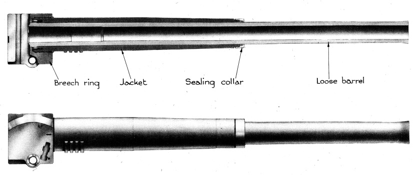
In contrast, the Mk II gun consisted of a barrel that was subjected to autofrettage to provide the necessary tensile strength and was a loose fit (as opposed to an interference fit) inside the jacket that extended to 41 inches from the muzzle. The barrel was tapered down along its length towards the muzzle although the muzzle end was given a slight flare. The barrel was retained in the jacket via the taper and by the breech ring at the back. The front of the jacket was threaded to take a sealing ring for the barrel.
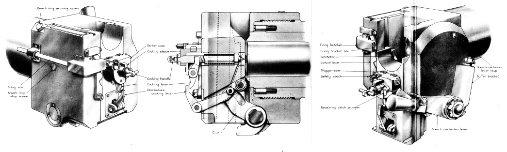
The Mk II gun was fitted with a vertical sliding block breech that was opened and closed by hand using a lever on the right-hand side of the breech. The complete breech could be easily removed to enable the gun to be disabled. The gun was fired using the firing handle on the left-hand side of the saddle that pushed against the firing rod on the left-hand side of the breech .
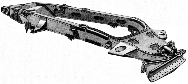
The barrel was attached to a recoil cylinder block that could slide backwards and forwards on grooves within the gun cradle as shown below. The cradle was fitted with trunnions to allow it to pivot on the gun saddle attached to the gun carriage.
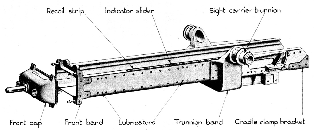
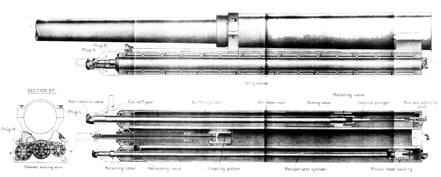
The cylinder block had four longitudinal cylinders bored in it. The right-hand cylinder was the hydraulic buffer that absorbed the energy of recoil with the centre and left-hand cylinders forming the recuperator that controlled the run out of the gun barrel after the recoil had been completed. Between the right-hand two cylinders and slightly above them was an oil reservoir cylinder for the hydraulic buffer.
The buffer cylinder contained a piston at the end of a rod attached to the front cap of the gun cradle. The piston consisted of both a sliding valve and a rotating valve that worked together to control the flow of oil as the gun recoiled. The inside of the buffer cylinder had a spiral groove that caused the rotating valve to rotate during recoil until the vanes in it and the sliding valve closed off the flow of oil and therefore brought the recoil to an end. The point at which the valves closed was controlled by the cut-off gear and the rotation of the piston rod and sliding valve which were mechanically linked to the elevation of the gun via a linkage on the right-hand side of cradle. With the gun horizontal, the recoil was limited to about 40 inches, whereas, at high elevations it was limited to about 16.5 inches in order to stop the breech hitting the ground. The back end of the piston rod also included a control plunger that was used to control the final stages of the run out of the gun
The left-hand recuperator cylinder also used a piston at the end of a rod attached to the front cap of the gun cradle. When the gun recoiled, oil in front of the piston was forced into the front of the central high pressure cylinder that included a floating piston with an air reservoir to the rear, initially at a pressure of 600 psi. This movement of oil helped to control the recoil but also pressurised the air in the high pressure cylinder and, after the recoil had been stopped, this compressed air forced the cylinder block forward to run out the gun.
The only major change to the Mk II gun was in 1942 when a muzzle brake was fitted to lesson the recoil when firing the 20 lb armour piecing shell with the maximum Charge Super. With it fitted, a counterbalance weight was added just in front of the breech ring.
QF 25-Pdr Ammunition
The Mk I gun fired fixed ammunition but the Mk II changed to shells and cartridges that were loaded separately into the breech to allow the propellant charges to be varied. This was necessary to allow the gun to provide the howitzer role with smaller charges and muzzle velocities. The propellant charges were of Cordite and made up of 3 portions, with each portion placed in a separate coloured bag. The No. 1 portion was in a red bag; the No. 2 portion was in a white bag; the No. 3 portion in a blue bag. They were contained within the cartridge case via two leather cups.
The gun was operated using 3 separate propellant charge options. Charge 1 made use of the No.1 charge portion only. Charge 2 used both the No. 1 and No. 2 charge portions. Charge 3 used all 3 charge portions. In additions to these charges, there was a separate Charge Super in its own bag that was used with the anti-tank armour-piecing round in order to provide the highest possible muzzle velocity.
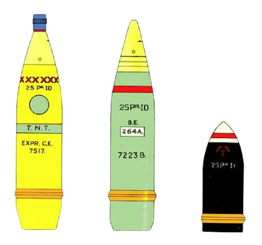
The projectiles used with the field gun were High Explosive (HE), Smoke Base-Ejecting (BE) and Armour Piecing (AP). The first two shells were streamlined and were reduced in diameter below the copper drive band. The HE shell contained a bursting charge of TNT along with a tube behind the fuze filled with Composition Exploding (CE) that was required to detonate the TNT. The rear of the tube formed a smoke box filled with pellets of red phosphorous. The HE shell was detonated using either a Direct Action No. 117 or No. 119 fuze. The shell could also be filled with Amatol that required a second exploder instead of the smoke box.
The smoke shell was base ejecting and contained a number of smoke containers. The shell used a No. 221 Time & Percussion fuze that set off a bursting charge below it that blew off the steel base of the shell releasing the smoke containers towards the ground. On the ground, the containers burnt and released dense clouds of smoke.
The AP shell was of solid steel but contained a tracer composition in a hole bored in the centre of the base. The AP shell weighed 20 lb.
The muzzle velocities produced by the different charges and shells were:
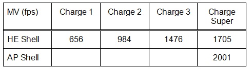
Using Charge Super and the maximum elevation, the maximum range of a HE shell was 13,4000 yd.
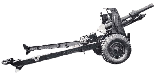
QF 25-Pdr Mk I Carriage
The Mk I carriage was designed to provide -5 to +40 degrees of elevation. The gun cradle was mounted on a saddle that pivoted on the front of the trail to provide traversing of the gun by up to 4 degrees to the left or right. Traversing was via a hand wheel on the lower left-hand side of the saddle. Elevation of the gun was via another hand wheel behind the traversing wheel.
A box trail was used with a space between the two arms to accommodate the recoil of the gun. It was fitted with a spade at the rear and a towing eye. The gun saddle was pivoted on the front cross member and the bullet proof gun shield was mounted on the front of the trail via brackets. The shield had an upper hinged portion that folded down for travelling. The pneumatic wheels were mounted either end of an axle that bolted to the underside of the trail. The wheels were fitted with drum brakes and were operated by a brake lever fitted on the right-hand side of the axle just behind the gun shield.
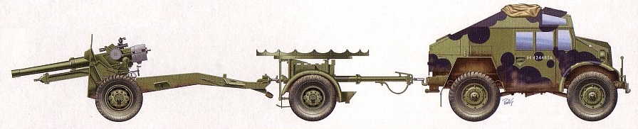
The field gun was normally towed behind a two-wheel trailer or limber that carried up to 32 complete rounds in 16 trays. It also carried other equipment and tools. Throughout most of the Second World War, the 25-pdr was normally towed with its limber behind a 4×4 field artillery tractor called a ‘Quad’. These were manufactured by Morris, Guy and Karrier in England, and, in greater numbers, as the Canadian Military Pattern field artillery tractor by Ford and Chevrolet in Canada. When being transported, the rear of the cradle was normally locked in position on the trail using a retaining catch in order to avoid damage to the elevating gear.
In contrast with the earlier QF 18-Pdr, the 25-pdr Mk I carriage used only one detachment member (the No. 3) to lay the gun who had a seat provided on the left-hand side of the gun. For this gun, the No. 2 stood to the right of the breech and was responsible for opening and closing the breech. He was also responsible for ramming home each shell since this was now separate from the cartridge case. The remainder of the gun detachment had the same roles as for the 18-pdrs: the No.1 commanded the detachment and provided larger traverses of the gun by moving the rear of the trail; the No. 4 was the loader and stood to the left of the breech; the No. 6 prepared both the fuzes and the cartridges that were then checked by the No. 5 before being passed to the No. 4.
The gun was normally deployed on a circulator firing platform that was held in position via a connecting stay to the trail. The platform allowed the gun to be traversed easily through 360 degrees and also meant that the spade at the back of the trail did not have to be used to stabilise the gun during firing. The platform was normally transported slung under the trail but could also be carried on the top of the trailer.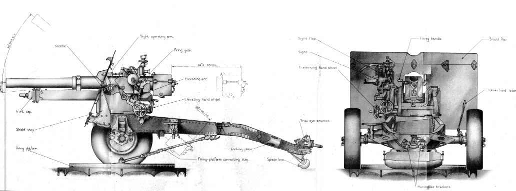
QF 25-Pdr Mk I Carriage Sighting
The QF 18-Pdr used a rocking bar sight that provided an independent line of sight during direct fire operations. This meant that the angle of sight (angle of elevation of the sight above the horizontal plane) could be set independent of the tangent elevation of the gun (the elevation of the gun above the angle of sight). The quadrant elevation of the gun (the actual elevation angle above the horizontal plane) was the sum of the angle of sight and the tangent elevation. The Mk I carriage then used a No. 7 dial sight during indirect fire operations. In order to account for the spin drift of the shells to the right at the longer ranges the trunnions were tilted down to the left by 1.5 degrees.
The sight assembly for the QF 25-Pdr was much more sophisticated and was essentially made up of three connected brackets. The inner sight supporting bracket (below left) pivoted on the gun saddle and rotated with the elevation of the gun via a parallel motion link connected to an operating arm keyed into the left-hand gun trunnion. The purpose of this arrangement was to allow the sights to be positioned conveniently for the gun layer some distance behind the trunnion. The supporting bracket included an elevation scale with a pointer on the gun saddle.
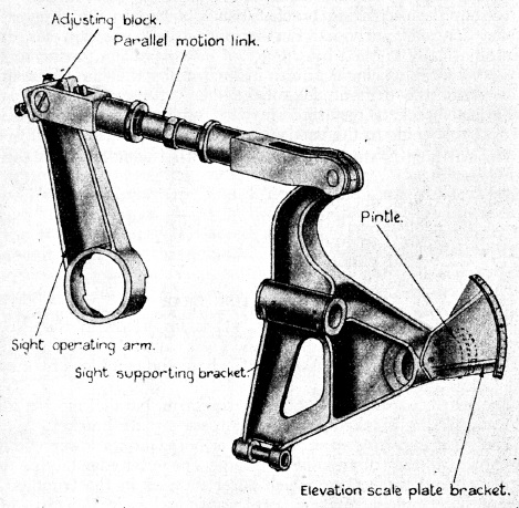
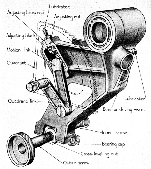
The sights used on the QF 25-Pdr are referred to as reciprocating (or oscillating) and were used to overcome the problem caused when the carriage wheels were not level, which was the normal. When this happened, the gun would inevitably shoot to the left or the right in the direction of the lowest wheel. On the QF 25-Pdr, this problem was overcome by pivoting an oscillating bracket (above right) on the sight supporting bracket so that the pivot axis was always parallel to the gun axis. In use, a cross bubble was used to allow the oscillating bracket and the sights to be aligned with the vertical plane with up to 10 degrees of adjustment possible either side of the vertical using the outer screw. With the oscillating bracket vertical, the sights would then have the same bearing in the horizontal plane as the gun and would therefore overcome the effect of the wheels not being level. In reality, when the bubble was levelled, the sights were given a slight tilt to the left (by a degree or so) in order to compensate for the basic spin drift of the projectiles in the same way as the trunnion tilt of the QF 18-Pdr.
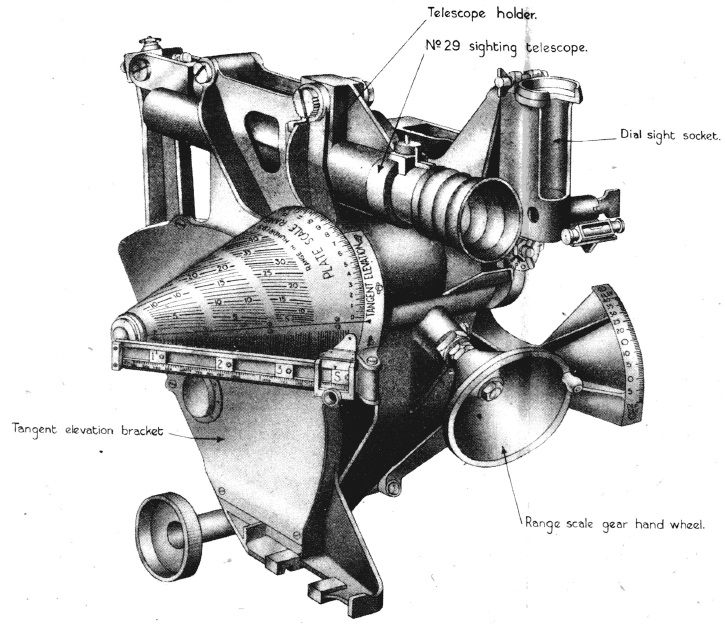
The third bracket in the sight assembly was the tangent elevation bracket that rotated in the vertical plane relative to the oscillating bracket. This bracket included a Probert range cone that allowed the required tangent elevation for the gun to be determined for a specified range and a specified projectile muzzle velocity. In British use, this type of sight is referred to as being calibrating since it avoided the need use a separate ‘gun rule’ to determine the required tangent elevation. The reader arm on the range cone had separate readers for Charge 1, 2, 3 & Super and allowed the muzzle velocity to be finely set for each charge in steps of 10 fps. The cone was engraved in units of 100 yds from 100 to 4,500 yds for Charge 1, 200 to 8,400 yds for Charge 2, 500 to 12,500 yds for Charge 3, and 10,500 to 14,000 yds for Charge Super. The Charge 1 pointer was normally set to 650 fps, Charge 2 reader to 975 fps, Charge 3 reader to 1,450 fps and Charge Super reader to 1,700 fps.
The range was set for a given charge by using the range scale hand wheel. Once set, the inside edge of the range cone indicated the required tangent elevation in the range 0-45 degrees. The hand wheel rotated the tangent elevation bracket via a quadrant gear by the indicated tangent elevation angle relative to the oscillating bracket. The range cone was also rotated at the same time by the range scale hand wheel in the opposite direction but was geared so that it rotated 360 deg over the tangent elevation range 0-45 degrees.
The sight clinometer was mounted on the left at the bottom of the tangent elevation bracket. The reading on the clinometer was equal to the quadrant elevation of the gun minus the tangent elevation set on the sight. Basically, it was used to set the angle of sight for the gun. If the tangent elevation was set to zero on the sight then the clinometer indicated the quadrant elevation of the gun. Both the No. 29 direct fire sighting telescope and the No. 7 or No. 9 dial sight were also mounted on the tangent elevation bracket.
In indirect fire mode, the required range was first set up on the range cone. The gun was then elevated until the sight clinometer read 0 degrees at which point the gun was set to the required tangent elevation. The required bearing for the gun was set up using the dial sight and was specified in terms of an offset bearing from a gun aiming point. A later No. 9 dial sight is shown below. Normally, the gun aiming point was a feature in the landscape that could be seen using the panoramic dial sight – it could be in front or behind the gun. To use the sight, the offset angle was set by rotating the sighting head to this angle with micrometers provided to allow this to be done accurately. The gun was then traversed until the gun aiming point was centered in the sight.
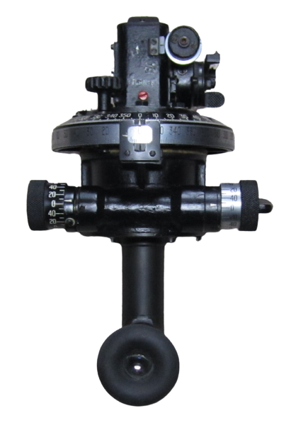
The mounting for the dial sight included the cross-bubble for the oscillating bracket and also included a drift correction that could be set for a given charge. This correction rotated the dial sight to the left by the set amount in order to correct the allowance for the spin drift of the projectiles.
The QF 25-pdr was also used in direct fire mode especially against tanks. After the required range had been set on the range drum, the sighting telescope was used to set the angle of sight using the traverse and elevation hand wheels. This mode of fire was often referred to as using open sights.
QF 25-Pdr Mk II & III Carriage
In Burma, a modified axle was used to reduce the width of the gun by 20 inches to make it easier to transport through jungles. The Mk II carriage was basically the formal adoption of this so-called Jury Axle modification that also included a narrower shield and Jeep like pneumatic wheels.
The Mk III carriage was a further modification just after WW2 that included joints in the trail to allow the front of the trail to be cranked up at a steeper angle and avoided the necessity of digging a pit for the end of the trail. It was used with a cranked dial sight adaptor.
Epitaph
The QF 25-Pdr Mk II entered service in 1940 and remained in use with the regular British Army until 1967 although it continued for some time with Territorial units beyond this. Famously, one was used in 1972 by the SAS in the battle of Mirbat in Oman. It remained in service with other countries long after this with the Irish Army only retiring their guns in 2009.
QF 25-Pdr Mk II Specifications
- Length: 15 ft 1 in
- Maximum Width: 6 ft 11.5 in
- Wheels: 2 ft 10 in pneumatic
- Weight of Gun & Carriage: 25 cwt 21 lb
- Length of Gun Barrel: 8 ft 1 in
- Length of Bore: 7 ft 8 in
- Bore: 3.45 in (87.6 mm)
- Weight of Gun & Breech: 8 cwt 104 lb
- Type of Ammunition: Shell and cartridge case loaded separately
- Weight of Shell: 25 lb (20 lb AP shell)
- Muzzle Velocity: 656-2001 fps
- Maximum Range: 13,400 yds (HE Shell and Charge Super)
- Trail: Box trail
- Recoil System: Hydro-pneumatic
- Maximum Recoil: 42 inch
- Rifling: Polygroove with plain section
- Length of Rifling: 6 ft 2 in
- Twist: Right-hand twist with 1 turn in 20 calibres
- Grooves: 26
- Firing Method: Percussion
- Elevation: -5° to +40°
- Traverse: -4° left to +4° right
![]()