

The legendary field gun used throughout WW1 by the French Army was designated the Matériel de 75mm Mle 1897 and was first adopted in 1898. Due to its fame, it is often referred to as the French 75, the 75 or the Soixante-Quinze (French for 75). It was the first, so-called, quick-firing field gun used in any army and pre-dated the equivalent British Ordnance QF 18-Pounder by 6 years. Its great technological breakthrough was the adoption of an effective hydro-pneumatic recoil system that enabled up to 20 rounds a minute to be fired without having to reset the gun sights.
The long stroke recoil system used by the M1897 was based in part on the design developed by Konrad Haussner while working at the Prussian Ingolstadt arsenal. However, in 1888, while working at Krupp, Haussner tried to get the firm to develop his design without success. Haussner therefore left the company and joined Grusonwerk AG where further work was carried out and a number of experimental guns were built using recoil systems based on his ideas. Unfortunately for Haussner, in 1893, the company was then taken over by Krupp. Krupp carried out tests on the experimental guns but decided that the technical challenges were too great especially in regard to leakage of hydraulic fluid and they abandoned the project. This prompted Haussner to contact Heinrich Erhardt in 1895 who had founded Rheinische Metallwaren- und Maschinenfabrik AG (now Rheinmetall AG) in 1889. Haussner then worked as an employee at Erhardt’s factory in Zella St. Blasii from 1896 to continue development of the recoil technology. This was largely completed later that year providing Erhardt with a recoil system suitable for field service. A few years later in 1900, the British Army placed a secret order for 100 or so Erhardt quick-firing guns for use in the 2nd Boer War (1899-1902). These were designated the Ordnance QF 15-Pounders and shown below.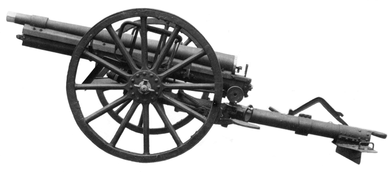
In the meantime, in January 1892, news of the original Haussner patent reached the French Director of Artillery, General Charles Mathieu. He consulted with the Artillery Technical Committee and, as a result, developed specifications for a recoil-absorbing 75mm gun. The committee’s president approached the War Ministry’s artillery workshop at Puteaux, whose director, Lieutenant-Colonel Joseph-Albert Deport, took on the challenge of developing a suitable field gun. In 1894, six of the resulting prototypes were ordered. Although they were successful in being able to fire up to twenty-two rounds per minute without needing to be re-laid in between, the hydro-pneumatic recoil system was far from perfect and leaked hydraulic fluid past the seals in the floating piston that proved to be easily damaged. At this point Deport, disgruntled at receiving no promotion, left for a private arms firm and the project passed over to Captain Charles-Etienne Sainte-Claire Deville, soon assisted by Captain Emile Rimailho, both (like Deport) graduates of the army’s elite engineering school, the Ecole Polytechnique. Over the next 3 or so years, they designed an entirely new recoil system that overcame the previous problems. The resulting field gun was designated the Matériel de 75mm Mle 1897 and was put into production starting in 1898 but was kept a secret until Bastille Day 1899.
During WW1. The field gun was also used by the US Expeditionary Force in WW1 who designated it the M1897. Most of the material described below is taken from the technical manuals issued by the US War Department on their version of the Mle 1897 field gun.
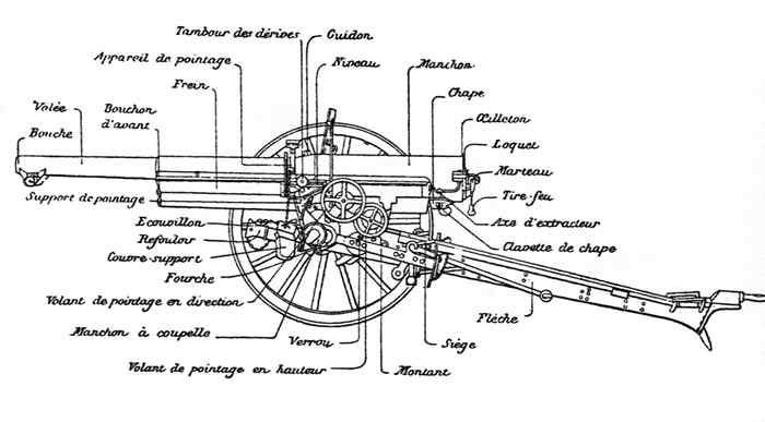
One of the issues in describing the field gun from another country is what terminology to use. Rather than using a translation of the French terms, the terminology used by the US Army for their version of the gun will generally be applied; for example, the US used the term ‘rocker’ which in French terminology was called the ‘Berceau de Pointage’ or pointing cradle. The term ‘recoil mechanism’ is also used here, whereas, the correct French term applied to the Mle 1897 was ‘Frein’ or brake.
The Mle 1897 carriage consisted of a narrow box trail with an axle mounted at the front with wooden spoked wheels with steel tyres at either end. The trail was fitted with a towing eye at the rear together with a spade to keep the carriage in position when firing. The wheels were fitted with external brake shoes at the back to also help with keeping the gun stable during firing. The gun shield was mounted on the front of the trail via brackets and support stays.

The gun cradle housing the recoil mechanism was fitted with trunnions that pivoted on the front of the trail. The Mle 1897 was very similar to operate as the equivalent British Ordnance QF 18-pounder and also used two-man laying with seats provided on either side of the breech. The right-hand gun crew member was responsible for setting the range of the gun and was provided with a hand wheel and range drum for this purpose. He was also responsible for opening and closing the breech and for firing the weapon using a lanyard attached to a spring loaded hammer on the back of the breech.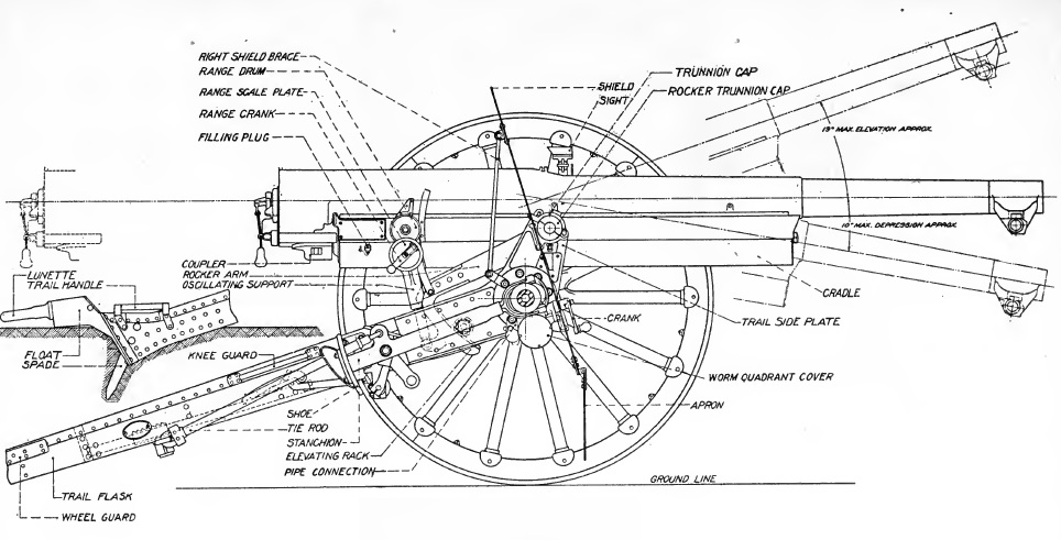
As with the British field gun, the left-hand crew member was responsible for setting the sights on to the target. He did this using the M1901 collimator sight mounted next to the left-hand gun trunnion using the two hand wheels provided. The upper larger hand wheel traversed the gun by up to 3 degrees to the left and right. This was accomplished by moving the front of the trail, together with the gun and shield, along the threaded front axle via a worm gear. The lower hand wheel then set the angle of sight that was independent of the elevation applied to the gun as explained below.
The M1897 gun was towed behind a gun limber that was pulled by 6 horses. The limber housed 72 complete shells and was deployed to the left of the gun during action providing the gun crew with extra protection.
Gun Design
The Mle 1897 used a built-up gun with the four main parts being the rifled tube, the breech hoop that was shrunk on to the rear third of the tube, the jacket that extended over the middle third of the tube, and the muzzle hoop. The underside of the jacket included a framework that supported the gun in the cradle containing the recoil mechanism. This framework included two sets of rollers on either side that allowed the gun to move back and forth smoothly in the cradle during recoil. The rear of the breech hoop was threaded to take the breech and included a bracket to connect it to the piston rod in the recoil mechanism. The back of the breech loop included a rear gun sight with the front sight being on the jacket. It also included a pair of leveling plates on the top surface along the centre line on which the gunner’s clinometer could be mounted in order to set the elevation of the gun. The muzzle hoop was fitted with castings underneath that contained a pair of rollers that supported the end of the gun on the ground when it was being moved.

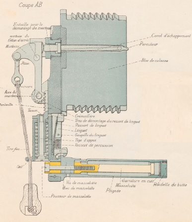
The Mle 1897 was fitted with a Nordenfelt eccentric screw breech. In this design, the cylindrical breech block rotates in the thread cut in the end of the breech loop that is offset downwards (eccentric) from the centre line of the bore. The cylindrical breech block incorporated an offset U-shaped longitudinal channel that allowed a projectile to be loaded through it into the gun chamber when the breech block was rotated to the open position. When the breech block was rotated clockwise though 155 degrees, this screwed the solid part of the breech block against the cartridge. In the centre of this part of the breech block was a firing pin. To fire the gun, the hammer at the back of the breech block was pulled back using the lanyard provided and, when let go, struck the back of the firing pin to fire the cartridge. When the breech block was opened, the old cartridge was automatically extracted.

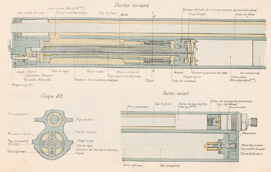
Recoil Mechanism
The recoil mechanism consisted of two longitudinal cylinders one above the other bored in the gun cradle. The smaller diameter upper cylinder was the hydraulic buffer used to absorb the energy of the recoil. It contained a piston at the end of a rod attached to the back of the gun’s breech hoop and was filled with hydraulic oil. When the gun was fired, the oil was forced backwards by the piston into the lower cylinder which formed the recuperator. Inside this cylinder was a floating piston with compressed air to the front. As the gun recoiled, the hydraulic fluid forced out of the upper cylinder pushed the floating piston forward further compressing the air at the other end. When the recoil was brought to a stop, the compressed air then forced the oil back into the buffer cylinder returning the gun to battery at the same time. It took about 2 s to run out the gun again after firing theoretically allowing a rate of fire of up to 30 rounds per minute. The key breakthrough with the M1897 was the design of its floating piston that had to provide a durable seal to prevent leakage of hydraulic oil and compressed air past it.
Gun Laying
An independent line of sight was provided on the Mle 1897 by the use of the rocker shown below (Berceau in French). This was essentially a bracket with two arms joined together at the rear that pivoted on the gun trunnions on either side of the carriage. The M1901 gun sight was attached adjacent to the trunnion on the left-hand arm of the rocker. A toothed quadrant projected down from the back of the rocker and engaged with a toothed shaft driven by the left hand elevating hand wheel. Turning this hand wheel raised or lowered the rocker along with the M1901 sight assembly.
The gun cradle was supported by the rocker via a screw jack that attached to the back of its toothed quadrant bracket. The screw jack was operated by the right hand elevating hand wheel and therefore applied tangent elevation to the gun. Another toothed quadrant (Sectour de Hausse) projecting upwards from the back of the rocker was used to operate the range dial on the right-hand side of the gun. Both the range dial and its toothed quadrant were graduated in metres up to 8,500 m.
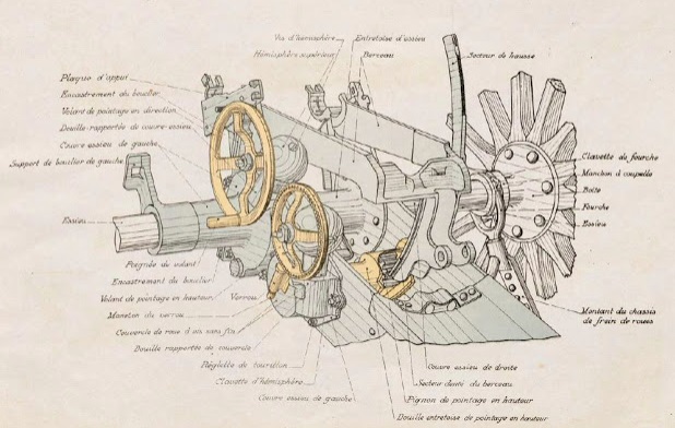
In direct fire mode, the elevation of the gun above the horizontal plane (the so-called Quadrant Elevation) needed to take into account two separate features of the target: its elevation relative to that of the gun, and the slant range between target and the gun. The Quadrant Elevation required therefore needed to be split between the angle of sight (the apparent elevation angle of the target relative to the horizontal plane at the gun trunnions) and the tangent elevation (the elevation above the angle of sight) required to achieve a particular slant range for the shell. The gun layer therefore used his hand wheels to put the collimator sight on to the target that set up both the bearing and the angle of sight. The right-hand crew member then used his hand wheel to set the tangent elevation of the gun to produce the required range to the target. The use of the rocker enabled these two operations to be independent of each other.
Gun Sights
The sights on the Ordnance QF 18-Pounder used by the British Army during WW1 employed sights graduated in degrees. In contrast, the M1901 sight used on the Mle 1897 was graduated in mils; rather than milli-radians, the mils used were the equivalent of the modern NATO mils with 6400 mils per degree.
The M1897 was fitted with the M1901 sight assembly that was mounted on the rocker bracket close to the left-hand gun trunnion. Unfortunately, since the trunnions were in front of the gun shield, so was the sight which consequently then had to be protected by its own small armoured plate (missing in picture below) leaving a very big hole in the main gun shield.

Rather than using a conventional telescope as the direct fire aiming device, the M1901 used a collimating sight. The sight itself consisted of a rectangular hood through which the target was viewed together with a small collimator in the lower part. The collimator generated a cross-hair reticule in the field of view of the sight effectively focused at infinity. Therefore, what the gun layer saw when looking through the sight hood was the target with the reticule superimposed on it with very little parallax. In use, the gun layer positioned his head about 10 inches behind the sight to use it properly.
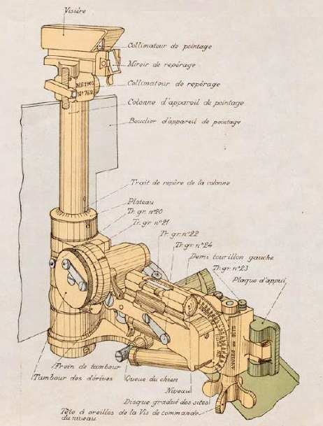
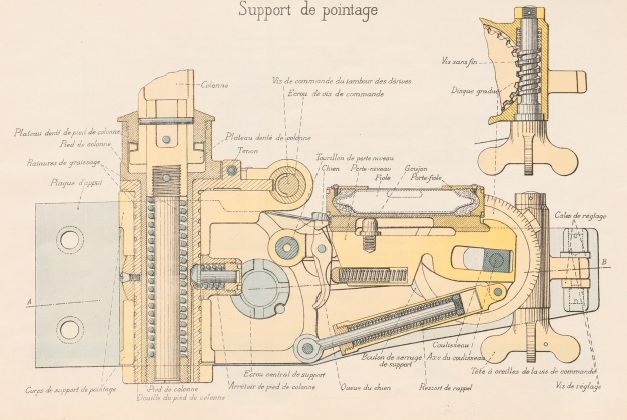
The M1901 sight assembly consisted of the sight mounti bracket, the deflection mechanism and the angle of sight mechanism. The sight mount bracket was rigidly attached to the rocker and, at the front end, provided a socket to take the collimating sight mounting tube. The top of the socket included an azimuth or deflection scale marked in units of 100 mils (5.625 degrees). The azimuth bearing could be changed in units of 100 mils on the socket scale by first depressing the sight column to allow it to be freely rotated. Finer adjustment was then provided by the deflection drum that was graduated from 0-100 mils. In direct fire mode, these adjustments were used to provide the necessary deflection to account for the right-hand spin drift of the projectiles. In all fire modes, it was also used to account for the effect of the carriage wheels not being level that resulted in rotation of the bearing of the projectiles in the direction of the lower wheel.
The sight mount was also provided with an angle of sight mechanism that incorporated a detachable clinometer that was intended for use in indirect fire mode. On the British Ordnance QF 18-Pounder, the sight clinometer provided an adjustment of ±20 degrees relative to the sight mount but on the Mle 1897 sight this adjustment was provided by the separate angle of sight mechanism. In this case, the clinometer was mounted on a bracket that pivoted on the sight mount bracket at the front and was tilted up and down at the back by the adjustment mechanism. This consisted of a winged adjustment knob that rotated a drum with the angle of sight graduated on a circular scale from -100 mils to + 100 mils. As the drum was turned, the end of the clinometer bracket was raised or lowered via an eccentric pin. In practice, the angle of sight was set on the scale and then the elevation of the rocker adjusted to give zero bubble on the clinometer.
To use the Mle 1897 in indirect mode, the required bearing and quadrant elevation of the gun had to be set based on calculations by a gun plotting officer. With the British Ordnance QF 18-Pounder, a panoramic dial sight was used to set the bearing for the gun. This was accomplished by using the dial sight to view a suitable distant aiming point (for example, a church spire) and by then traversing the gun to give the required offset bearing from it. With the British dial sight, this could all be accomplished without the gun layer (No. 3) having to move from his seat – he simply rotated the viewing head on the sight anywhere from 0-360 degrees in azimuth. However, the M1901 sight was not panoramic and, although it could be rotated through 360 degrees, the gunner had to move around to in front of the shield if the aiming point was behind the gun. In this case, since the sight might not see over the gun shield an extension tube sometimes had to be used to raise the sight to make this possible. In order to set the quadrant elevation of the gun, a clinometer was mounted on the breech hoop
Ammunition
At the beginning WW1, the Mle 18975 fired two main types of shells: a high explosive (HE) shell and a shrapnel shell. The HE shell weighed 5.3 kg and was thin walled and filled with a picric acid explosive called Melinite. It was fitted with the 24/31 Model 1899-08 percussion fuze that was modified in 1908 to provide a 0.05 s delay. This was intended to be used with HE shells fired at low angles that were exploded by the delay after they ricocheted off the ground.
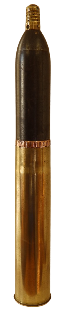
The shrapnel shell weighed 7.24 kg and was filled with 290 lead/antimony balls. The 22/31 Mod 1897 Time & Percussion fuze was used to provide a time delay of up to 24 s but also contained a percussion detonator to set off the shell in case it hit the ground first. When the time fuze had burned through, a central tube conducted the flash to a bursting charge at the base of the shell separated from the shrapnel balls by a steel disk. Detonation of the bursting charge then resulted in the front of the shell and the shrapnel balls being ejected at high speed to spray the ground ahead of the shell.
Later in WW1, various other types of shell were developed, many for anti-aircraft use, including a streamlined HE shell giving the gun an extended range of 11,000 m.
Mle 1897 Specifications
- Length: 4.45 m
- Maximum Width: 2.0 m
- Wheels: 4 ft 8 in
- Weight of Gun & Carriage: 1,544 kg
- Length of Gun Barrel: 2.72 m
- Bore: 75 mm
- Weight of Gun & Breech: 9 cwt
- Muzzle Velocity: 1615 fps
- Maximum Range: 8,500 m with HE shell (11,000 m with later shell)
- Trail: Narrow box trail
- Recoil System: hydro-pneumatic
- Maximum Recoil: 122 cm
- Rifling: Polygroove with modified plain section
- Length of Rifling: 2.23 m
- Twist: Right-hand twist
- Grooves: 24
- Firing Method: Percussion
- Elevation: -11° to +18°
- Traverse: -3° left to +3° right
![]()