

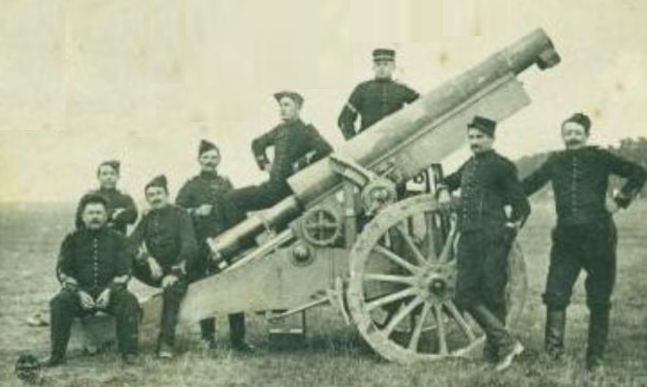
The Canon de 155 C Mle 1904 TR (tir rapide or rapid fire) Rimailho or CTR was designed by Captain Emile Rimailho while working at the French arsenal at Puteaux (Atelier de Construction de Puteaux). Together with Captain Charles-Etienne Sainte-Claire Deville, he had a few years earlier worked on the design of the famous Canon de 75 Mle 1897 field gun.
The CTR was designed as a heavier field gun with a reasonably fast (5-6 rpm) rate of fire to complement the lighter Mle 1897. At the outbreak of WW1, there were just over 100 CTR’s available but it was soon found that their maximum range was inadequate for the type of trench warfare that had developed. In order to increase the range, a larger propellant charge was introduced but this wore the barrels out very quickly. As a result of this, the French Army had to rely on the obsolete Canon de L Mle 1877 de Bange which, at least, was available in large numbers until more modern 155 mm guns could be introduced starting with the Canon de 155 L Mle 1877/14 Schneider.
Carriage
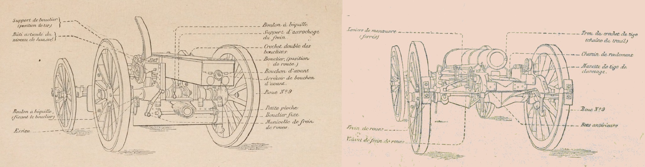
The CTR used a box trail with side arms joined at the front and rear that left room for the gun to recoil in between. The trail was fitted with wooden wheels and used a pair of metal shoes on the end of a frame that pivoted about the wheel axle and could be locked into position under the wheels to prevent the carriage recoiling during firing. The trail was fitted with a small shield to protect the gunners and was equipped with a spade at the rear to stabilise the gun during firing.
The CTR required two man laying with the left-hand crew member operating the sights and being responsible for adjusting the traverse and the angle of sight. The right-hand crew man was responsible for setting the tangent elevation of the gun to achieve the required firing range. The left-hand crew member was provided with two concentric hand wheels, with the smaller outer one (volant de direction) controlling the traverse and the larger inner one (volant de site) used to adjust the angle of sight. As with many French field guns of that period, traverse was provided by moving the front of the trail sideways on the wheel axle to provide about 2.5 degs of movement to the left or right. The traversing hand wheel rotated a horizontal pinion via a gear train that engaged with teeth cut into the wheel axle such that, when the pinion was turned via the hand wheel, the front of the trail was moved sideways relative to the axle.
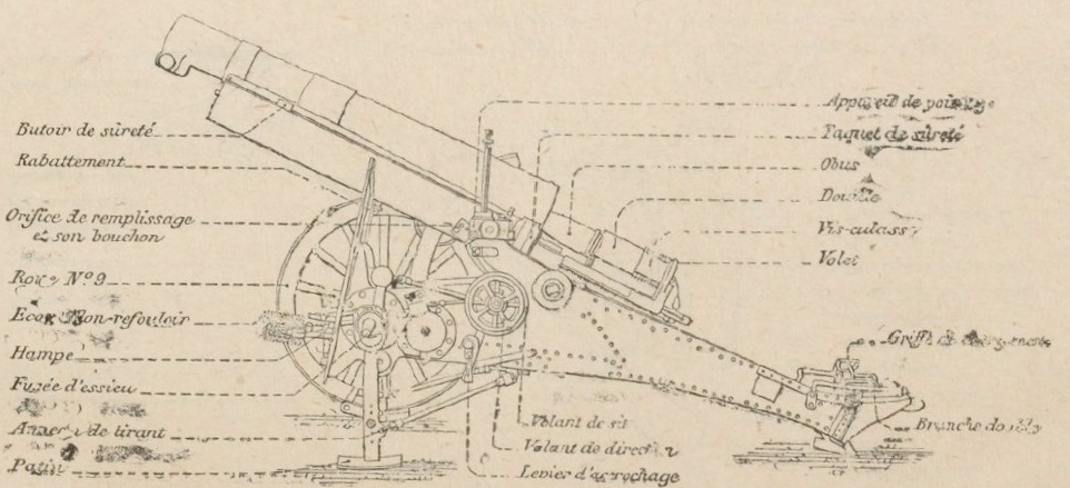
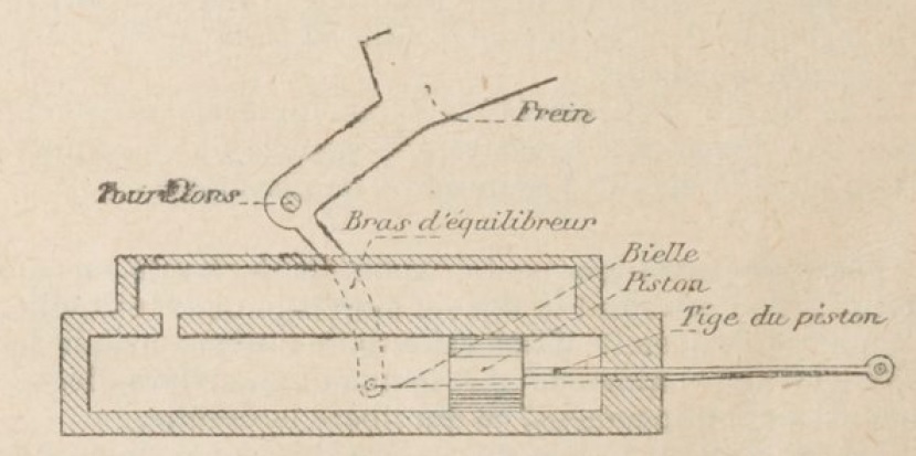
The gun was elevated via a large elevating arc on the right-hand side of the gun. Unusually, the trunnions (tourillon) for the gun were mounted at the rear of the cradle in order to minimise breech movement when the gun was elevated making loading ammunition easier. However, in order to balance the gun, a pneumatic balancer was used which was mounted under the rear of the cradle connected to it via a bracket as shown.
The gun was elevated using the geared hand crank mechanism (manivelle de hause) fixed to the cradle which acted against the teeth in the elevation arc. The outside of the arc was graduated in degrees. However, in order to set the angle of site, the inner hand wheel on the left of the carriage (volant de site) rotated a pinion on the right-hand side of the front of the carriage which also engaged with the teeth in the elevating arc. This had the effect of rotating the arc about the right-hand trunnion adding the angle of sight to the elevation of the gun. In artillery terms, the resulting quadrant elevation of the gun was the sum of the angle of sight and the tangent elevation set by the right-hand crew member (see sights section for a fuller explanation).

The CTR was transported by sliding the gun on to a separate 4 wheel carriage to be pulled by horses with the remainder of the carriage pulled in a similar way after a second pair of wheels was added to the rear of the trail.
Gun Design
It is believed that the CTR gun was based on that of the Obusier de 155 mm C Mle 1881 which consisted of an inner rifled tube with a steel full length jacket struck on to it. Both guns were 2.4 m or 15.5 calibres in length. While the Mle 1881 used a de Bange breech and fired bagged cartridges, the CTR used brass cartridges with an interrupted screw breech.
In order to achieve a rate of fire of 5-6 rounds per minutes, the CTR used an automatically opening breech. To achieve this, the breech screw (volet) was attached to a support bracket (verrou du volet) that was mounted on a pair of breech rods (tiges de culasse) with a traverse bracket at the rear such that, when the gun recoiled, the gun and breech pushed against the rear bracket and extended the rods out of the back of the cradle. As the gun started to return to battery, the rods latched in the extended position while the gun pulled the breech support bracket forward along the rods. The inside of the rod ends were toothed and, as the breech support bracket moved forward on them, these teeth rotated a pinion (pignon du volet) inside the bracket which acted against the toothed section (secteur dente de ois-culasse) on the outside of the breech plug. This rotated the breech plug and unlocked it, leaving it stopped on the breech rods while the gun returned to battery.

With the breech plug clear of the breech, it was then possible to position the next shell in the mouth of the breech with its end supported on the loading post (planchette de chargement) with the cartridge case positioned behind it. Underneath the breech rods were toothed racks (cremaillere de tige). These were engaged by pinions rotated by the hand wheel (volant de culasse) on the right of the carriage which was used to wind the breech rods forward forcing the next round into the chamber and the breech plug into the breech opening. With the breech plug fully home, the last few inches of movement of the breech rods rotated the breech plug again and locked it into position.
The CTR was fired by pulling back on the hammer with the short lanyard provided which, when released, struck a firing pin which, in turn, struck the primer at the base of the metallic cartridge. When the gun recoiled and the started to move forward again, the loading post served as an extractor for the spent cartridge.
The semi-automatic breech mechanism was very complicated but sped up the loading process by eliminating the time normally taken to lower the elevation of the gun to make conventional manual loading possible. Compared with the 15 rpm possible with the Mle 1897, the maximum rate of firing of the CTR was a more modest 5-6 rpm. However, compared with the 1 rpm of the Mle 1877, this was a significant improvement.
Recoil System
Details of the recoil system used on the CTR are not known but it assumed that it was based on that developed at the state arsenal at Puteaux for the Mle 1897 a few years earlier. The recoil system for the latter was a little unusual compared with later systems because it used a combined hydraulic buffer and recuperator instead of independent functions for each. If the CTR recoil system followed the same approach then the cradle housed at least two cylinders with one of them forming the hydraulic buffer and the other forming the recuperator.
Within the hydraulic cylinder was a piston on the end of a rod attached to the breech ring of the gun. The piston was positioned at the front of the cylinder when the gun was in battery and, as the gun recoiled, the oil in the cylinder behind the piston was forced through small ports into the recuperator cylinder. Inside this cylinder was a floating piston with oil to the rear and air to the front. As the gun recoiled, the displaced oil from the hydraulic cylinder forced the floating piston forward compressing the air in front of it. The gun’s recoil energy was absorbed by a combination of the restriction to the flow of oil caused by the hydraulic cylinder ports and by compressing the air in the recuperator cylinders.
After the recoil energy had been adsorbed and the gun brought to a stop, the increased air pressure in the recuperator cylinder then forced the gun forward again into battery. The air in this cylinder had to be maintained at a pressure of about 600 psi. The recoil distance was about 1.0 m.
Sights
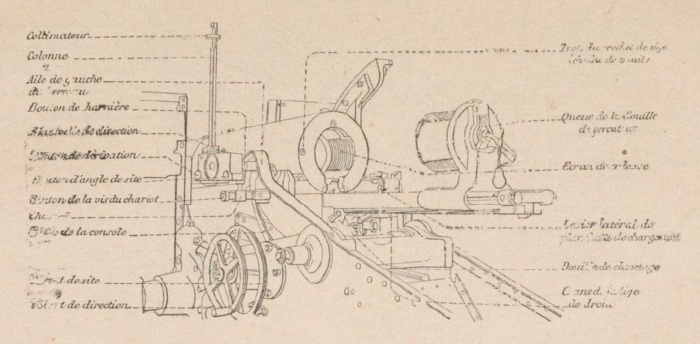
The CTR was developed before the advent of the panoramic telescope sight which was invented by Goertz in Germany in 1906. Instead the CTR made use of a collimator sight on a rotatable column in much the same way as the Mle 1897.
The CTR sights were reciprocating to overcome the problem caused by the carriage wheels not being level. The basic requirement is that the sights should operate in the same vertical plane as the gun and, the problem caused by the wheels (and gun trunnions) not being level, is that this vertical plane is rotated away from the centreline of the carriage in the direction of the lowest wheel. If not corrected, this will lead to a large sighting error especially at higher elevation angles for the gun.
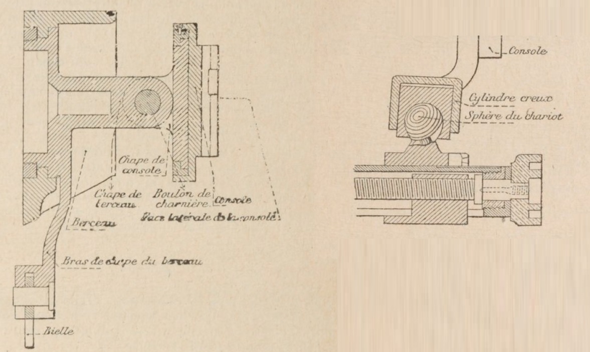
This problem is solved in a reciprocating sight by tilting the sights sideways to put them back into the same vertical plane as the gun. To do this, it must tilt about an axis that is kept parallel to the axis of the gun. The CTR sights were mounted on a large sight arm (aile gauche du berceau ) that pivoted on the left-hand gun trunnion and whose inclination was controlled by the inner hand wheel on the left of the carriage. The sight block (console) was mounted on the sight arm via a reciprocating bracket (chape de console) that was hinged in the middle and was free to rotate in both the sight arm and the sight block. The inner part of this bracket was fitted with an arm that was connected through a pivot to a rod (bielle de console) whose other end was connected through another pivot on the carriage. This arrangement formed a parallel motion mechanism that ensured the hinge on the reciprocating bracket rotated and always remained parallel to the gun as its elevation changed.
As shown below, the sight block was also connected to the sight arm via a sliding ball joint connected to a screw driven carriage (chariot). The lateral position of the carriage was adjusted via the knob provided which tilted the sight block about reciprocating bracket hinge allowing the sights to be adjusted to the same vertical plane as the gun. A transverse clinometer bubble (niveau tranversal) was provided on the front of the sight box to allow the adjustment to be made.

At the rear of the sight block was a knob provided to change the angle of sight with a dial on top of the block showing the setting. This altered the inclination of the longitudinal clinometer on the sight block (niveau longitinal) which was levelled using the inner hand wheel on the left of the carriage to apply this angle of sight to the gun.
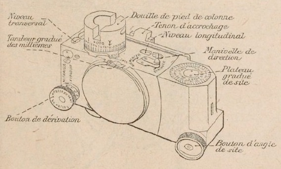
In indirect fire, the target direction was specified as an offset bearing relative to an aiming point set up for the gun which could, for example, be a prominent feature on the landscape. To lay the gun required this relative bearing to be set on the sight. This was done by unlocking the collimator column and rotating it by hand to give the coarse setting on the column dial and then using the small crank handle (manivelle de direction) to provide a fine adjustment using the drum on the side of the sight block. Once set, the gun was traversed until the aiming point was centred in the collimator at which point the gun was pointed in the target direction.
The sighting block also incorporated a knob on the side at the front to provide a deflection adjustment to take into account the effect of wind but also the spin drift which was different for the high explosive and Shrapnel shells. This deflection adjustment was applied to the collimator column setting.
Ammunition
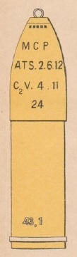
The CTR fired both high explosive and Shrapnel shells weighing a nominal 43 kg. As with the other 155 mm field guns used up to and during WW1, the CTR would have fired both the steel shells and shells made out of cast iron intended to reduce the cost of manufacture and to open up manufacturing to private forms.
The guns were unusual in using brass cartridge cases rather than bagged charges as used, for example, by the older Mle 1877. In the case of the CTR, this was to speed up the firing rate because handling bagged cartridges and swabbing out the breech afterwards of burning embers, took quite a bit of time. In addition, the semi-automatic breech used by the CTR only worked with brass cartridge cases.
Like all howitzers, the CTR made use of variable charges in order to use plunging shell fire at different ranges. A total of 6 different charges were used with Charge 0 being the most powerful and used when the maximum range possible was required. For a given charge, the maximum range was achieved with a tangent elevation of 40.5 degrees.
A wide range of fuzes were used with the shells ranging from super quick percussion to dual effect time and percussion.
Canon de 155 C Mle 1904 TR Rimailho Specifications
- Length: 4.7 m
- Wheels: Wooden 1.50 m in diameter
- Weight of Gun & Carriage: 3200 kg
- Length of Gun: 2.40 m or 15.5 calibres
- Bore: 15.5 cm
- Muzzle Velocity: 290 m/s
- Maximum Range: 6,280 m
- Trail: Box trail
- Recoil System: Hydro-pneumatic
- Maximum Recoil: 1.0 m
- Length of Rifling: 1.871 mm or 12.1 calibres
- Twist: Right-hand progressive with final 1 turn in 25 calibres at muzzle
- Grooves: 48
- Firing Method: Percussion
- Elevation: 0° to +60°
- Traverse: -2.5° left to +2.5° right
![]()