

The War Office purchased four 9.45-inch heavy siege howitzers in 1900 from Skoda in Austria for use in attacking the formidable forts around Pretoria during the 2nd Boer War (1899-1902). These guns were designated the 9.45-Inch BL Howitzer. However, by the time the British reached the outskirts of Pretoria, the forts had already been stripped of both guns and soldiers as they were needed elsewhere, and so offered very little resistance.
The main issue found with the Skoda howitzer was the limited minimum elevation angle of 44 degrees that restricted the maximum range – this effectively made them mortars rather than howitzers in the accepted sense. The War Office therefore decided to develop its own heavy siege howitzer. The design accepted originated at the Coventry Ordnance Works that was a consortium of large naval firms. A prototype weapon was built in 1913 and sent for trails in early 1914. By October 1914, it was in action on the Western front and designated the 9.2-Inch BL Howitzer. Production guns entered service in 1915 and, by the end of the war, some 450 guns had been supplied to the British Army. The prototype gun named ‘Mother’ is now on display at the Imperial War Museum in London.
Although the Mk I was designed by the Coventry Ordnance Works, it was also manufactured by Vickers and Bethlehem Steel in the US. However, early on in the war, the senior artillery commander in France requested improvements and a significant increase in range. The result was the Mk II gun introduced in 1916 that was designed and built by Vickers. In total, just over 600 complete guns of both marks were manufactured between 1914-18 going to both the British and US armies. It was designed for anti-battery use and for attacking fortified strong points.

9.2-Inch BL Howitzer Mk I
Gun Design
The gun consisted of a rifled A-tube, muzzle stop ring, layers of steel wire, jacket, breech bush and breech ring. A number of layers of steel wire were wound over the A-tube from the breech to the muzzle stop ring. The jacket was then shrunk fit over the steel wire layers and the muzzle stop ring. The breech bush was screwed into the end of the A-tube and then the breech ring shrunk and screwed into the rear of the jacket. The jacket was fitted with two longitudinal projections forming the guides for it to recoil in the gun cradle.
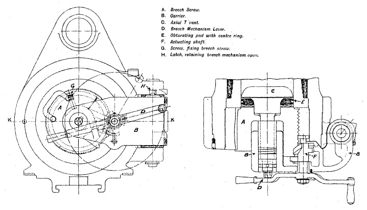
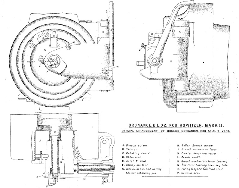
An interrupted thread breech screw was used that was supported on a carrier which was hinged on the right of the breech ring. The breech was opened by turning the lever on the back of the mechanism that rotated the breech screw to unlock it after which the breech screw was then swung out of the way. The breech was closed by swinging the breech screw into the breech and then rotating the lever to lock it. The breech was sealed during firing by means of the obturator pad behind the mushroom shaped axial T-vent. Locking the breech, pressed the obturator pad into the coned seating in the breech. When the cartridge was fired, this forced the mushroom of the vent backwards compressing the obturator pad further against the sides of the breech and thus sealing it against the propellant gases.
The howitzer was originally designed to be fired using a T-tubes. These T-shaped devices consisted of a vent plug filled with combustible pellets and a cross piece containing a friction igniter with loop for the firing lanyard. The vent plug was inserted into the axial T-vent in the breech and was designed to seal the vent when the cartridge ignited. However, later versions of the breech were fitted with a percussion lock and were used with a ‘Tube, Percussion, S.A Cartridge’ that fired through the centre of the axial T-vent. Again, a lanyard was used to fire the percussion cartridge.
Carriage Design
The Mk I carriage allowed the howitzer to be fired from 15 degrees of elevation to 55 degrees of elevation with the gun being loaded using a depression angle of 3 degrees. The carriage allowed 30 degree of traverse to the left or the right. The gun was mounted in a cylindrical cradle in which it recoiled and was fitted with a recoil system that consisted of a hydraulic buffer and a hydro-pneumatic recuperator. The cradle was fitted with trunnions to allow it to rotate on the carriage.
The gun could be elevated using the hand wheels on either side of the carriage. The gear on the left was ‘slow motion’ and elevated both the gun and sights. The gear on the right was ‘quick motion’ and was used to depress the gun for loading and then to raise it back up to the correct elevation for firing. The gun was elevated by means of an elevating arc under the cradle. However, the sights were rotated about the left-hand trunnion via a separate elevating arc to the left of the gun elevating arc. When the left-hand hand wheel was operated, both elevating arcs were moved together and so the sights elevated with the gun. However, by operating a foot lever on the right-hand side of the carriage a clutch disengaged both the sight elevating arc and the left-hand elevating hand wheels from the gun elevating arc. This allowed the gun to be quickly depressed for loading without moving the sights and quickly returned to the correct elevation prior to firing.

The carriage was made up of a bed that was rectangular in form and consisted of two box section girders with a pivot block at the front and a transom to facilitate transportation at the rear. The carriage body pivoted on rollers on the front pivot block and traversed on a roller track toward the rear of the bed that included a traversing rack. A hand wheel on the left of the carriage operated a vertical pinion that engaged with the rack to provide up to 30 degrees of traverse to the left and or right. The transom was fitted to the rear of the girders and incorporated a bracket for engaging with the transport limber.
The carriage body consisted of two side brackets that were connected by a front and rear transom. The front transom interfaced with the pivot block while the rear transom interfaced with the traversing mechanism. The carriage body provided the pivot bearings for the gun cradle. A number of platforms were mounted on the carriage body for use by the gun detachment to operate the gun mechanisms. A large platform was provided at the rear to facilitate the loading of the gun. A loading gear was provided on the left-hand side of the carriage that including a winch handle for elevating the loading arm supporting the loading tray.
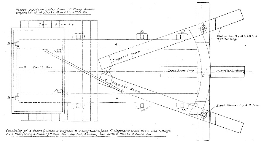
The howitzer was normally deployed in the field bolted down to a holdfast frame that was buried into the ground. This frame provided a stable platform for the howitzer and included a collapsible earth box on the front holding approximately 11 tons of earth to prevent the gun pivoting backwards when fired.
Recoil Mechanism
The recoil mechanism consisted of a hydraulic buffer mounted on the cradle above the gun and a hydro-pneumatic recuperator mounted beneath it. The hydraulic buffer recoiled with the gun with ribs fitted to enable it to slide in grooves on the cradle. The hydraulic piston remained stationary during recoil attached via a rod to the cradle. The piston was fitted with two ports for the passage of oil but also included a rotating valve that was keyed into two spiral grooves in the wall of the hydraulic cylinder forcing it to rotate as the gun recoiled. The rotating valve also had two holes in it that aligned with those in the piston at the start of recoil to allow the maximum oil flow rate but, as the gun recoiled and the rotating valve rotated, the openings closed off bringing the recoil to an end.

A cut-off gear was fitted to the gun whose purpose was to limit the length of recoil as a function of the gun’s elevation angle. The cut-off gear was mounted on the right-hand side of the cradle and caused the hydraulic piston rod to rotate by an amount determined by the elevation of the gun. The more the rod was rotated, the earlier the rotating valve cut off the flow of oil through the piston and the shorter the length of recoil. The length of recoil was 40 inches at 15 degrees reducing to 23 inches at 55 degrees. The cut-off gear was needed to prevent the breech hitting the ground or the carriage bed at the higher elevation angles.
The gun was fitted with a hydro-pneumatic recuperator mounted under the gun. The recuperator consisted of an air cylinder that remained stationary on the cradle when the gun recoiled. An hydraulic ram was connected to a bracket under the muzzle of the gun and was forced past a seal into the end of the recuperator cylinder when the gun recoiled. A long hollow floating piston was mounted inside the ram and air cylinder with oil in the ram in front of it. The main purpose of the floating piston was to ensure a positive pressure on the oil side of the piston seals to prevent air leakage. The diameter of the ram was less than that of the air cylinder so that, as the ram moved into the cylinder, it left a space between it and the cylinder into which oil had to flow. The net effect of this was that, when the gun recoiled back 40 inches along with the ram, the floating piston only moved 33 inches. The front of the floating piston was formed into a rod that passed through a seal in the front of the ram and provided a visual indication of how much oil was in the recuperator.

Gun Sights
The sight supporting bracket was fixed to a bracket that rotated on the left-hand gun trunnion and given the same elevation angle as the gun via an elevating arc under the cradle. The sights were oscillating or reciprocating in order to compensate for the gun trunnions not being perfectly level. This type of tilt caused the plane containing the projectile’s trajectory to be rotated in azimuth in the direction of the lowest trunnion. To compensate for this, an oscillating bracket was mounted on the sight supporting bracket that could be tilted about a pivot that was parallel to the gun axis. By using the cross bubble to make the oscillating plate vertical, this ensured the sights were in the same plane as the projectiles.
The sights themselves were mounted on a range bracket that pivoted in elevation on the oscillating bracket. A hand wheel was provided to rotate the range bracket and a dial ring indicated the elevation angle from 0-55 degrees in 5 minute steps. The range bracket mounted a rocking bar sight and a carrier for the dial sight. A longitudinal level was also fitted in order to provide a means for determining the quadrant elevation of the sight.
The rocking bar was provided with a fore sight and a back sight together with a deflection adjustment and scale gradated up to 5 degrees left or right. The rocking bar also provided mounts for a No. 4 sighting telescope. The Mk I sight was provided with an automatic mechanism for adjusting the angle of drift as a function of elevating angle. However, in the Mk II sight, this mechanism was omitted and the sight was given an offset instead that accounted for the angle of drift.

The required azimuth bearing for the gun was set using the No. 7 panoramic dial sight shown below. This consisted of a sighting head that could be rotated up to 360 degrees in azimuth using a pair of micrometer dials in combination with a large azimuth scale marked in degrees. A prism in the sighting head directed the field of view down into the body of the dial sight with a lower prism used at the bottom of the sight to then direct the field of view into the fixed eye piece. A correcting prism was employed in the centre of the dial sight to correct for the rotation of the image which would otherwise occur when the sighting head was rotated. The lower optics were also used to generated a set of crosshairs in the field of view with a small window provided adjacent to them to allow illumination for night firing.
The required target bearing was determined by a plotting officer using a map. It was defined as an offset angle from the gun’s aiming point. The aiming point was normally a clearly defined feature in the landscape which could be behind or in front of the gun. The required offset was set on the panoramic dial sight and the gun then traversed until the aiming point was centred in the sight at which point the gun had the correct target bearing.

9.2-Inch BL Howitzer Mk II
Gun Design
The Mk II gun was similar to the MK but was 37 inches longer to increase the maximum range from 10,060 yd to 13, 935 yd. It was generally similar to the Mk I gun with the main change being the use of an inner A-tube to allow easier re-sleeving of the gun when it became too worn. This was necessary because the much higher muzzle velocity for the Mk II gun resulted in greater wear of the bore compared with the Mk I gun. 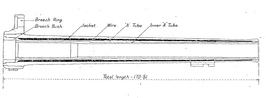
The Mk II gun was fitted with an interrupted Welin breech screw and a single motion Asbury breech mechanism. This meant that one pull on the lever rotated and unlocked the breech screw and then swung it clear of the breech.
Recoil Mechanism
The recoil mechanism was similar to that on the Mk I. A cut-off gear was fitted so that the length of recoil was 44 inches at 15 degrees reducing to 20 inches at 50 degrees.
Mk II Gun Carriage
The Mk II gun carriage was not compatible with the Mk I gun and vice versa. The two versions of the gun carriage were very similar with the main difference being a reduction in maximum elevation angle from 55 to 50 degrees.
Ammunition
The 9.2-Inch BL Howitzer used bagged cartridges with igniter powder sewn into the base.

It fired three types of shell: high explosive (HE), common pointed and gas.  The HE shells had a 4 calibre radius head (CRH) and contained Lyddite, Trotyl (TNT) or Amatol and were detonated using a nose mounted No. 101 percussion fuze or a No. 106 direct action percussion fuze. The shells weighed 290 lb.
The common pointed shell also had a 4 CRH nose and was filled with a gunpowder bursting charge that was detonated using a No.16 base fuze. This shell also weighed 290 lb.
The chemical shell was basically a HE shell converted to contain gas. It was also detonated using a percussion fuze.
Transporting the Gun
The howitzer was broken down into 3 separate loads for transportation. The cradle and carriage body in one, the bed in another and the gun in the third. The carriage body and bed were designed to have the axle trees and brakes bolted directly to them, whereas, the gun required a separate carriage on to which the gun was hoisted. The transport carriages were designed for both horse and mechanised towing, with the latter being the more common method.

9.2-Inch BL Howitzer Specifications
- Overall Height: 8 ft 6 inch (gun horizontal)
- Overall Length: 14 ft 2.5 inch (gun horizontal)
- Overall Width: 8 ft 0.5 inch
- Total Weight of Gun & Mount: 12 ton 19 cwt 92 lb
- Length of Gun Barrel: 11 ft 1.5 inch
- Length of Bore: 10 ft 1.5 inch
- Bore: 9.2 inch
- Weight of Gun & Breech: 3 ton 90 lb
- Muzzle Velocity: 1187 fps
- Maximum Range: 10,060 yd
- Recoil System: Hydro-pneumatic
- Maximum Recoil: 40 inch
- Rifling: Polygroove with plain section
- Length of Rifling: 9 ft 2 inch
- Twist: Right-hand twist with 1 turn in 15 calibres
- Grooves: 56
- Firing Method: Percussion with ‘Tube, Percussion, S.A. Cartridge’
- Elevation: -3° to +55°
- Traverse: -30° left to +30° right
9.2-Inch BL Howitzer Mk II Specifications
- Overall Height: 8 ft 6 inch (gun horizontal)
- Overall Length: 16 ft 2.5 inch (gun horizontal)
- Overall Width: 8 ft 0.5 inch
- Weight of Gun & Carriage: 15 ton 16 cwt 108 lb
- Length of Gun Barrel: 14 ft 2.5 inch
- Length of Bore: 13 ft 3 inch
- Bore: 9.2 inch
- Weight of Gun & Breech: 4 ton 5 cwt 56 lb
- Muzzle Velocity: 1500 fps
- Maximum Range: 13, 935 yd
- Recoil System: Hydro-pneumatic
- Maximum Recoil: 44 inch
- Rifling: Polygroove with plain section
- Length of Rifling: 9 ft 2 inch
- Twist: Right-hand twist with 1 turn in 25 calibres
- Grooves: 56
- Firing Method: Percussion with ‘Tube, Percussion, S.A. Cartridge
- Elevation: -3° to +50°
- Traverse: -30° left to +30° right
![]()