

In 1909, the French authorities invited proposals from the state arsenals for upgrading their antiquated Canon de 155 L Mle 1877 De Bange guns with a modern recoil system. This exercise was not successful and so in 1910 the two private firms of Schneider and FAMH (at St Chamond) were also invited to submit proposals. Eventually in 1913, a contract was awarded to Schneider to convert 120 guns which were designated the Canon de 155 L Mle 1877/14 Schneider or L14S but deliveries were delayed until 1916. Schneider based their design on the carriage developed for the Canon de 105 L Mle 1913 Schneider.

Carriage
The L14S was mounted on a box trail with side arms in the front half that allowed space for the gun to recoil at higher elevation angles. A very large shield was mounted on the front of the trail to protect the gun crew with the side plates hinged to allow for stowage during transport and with a hinged opening to allow for forward observation of the gun sights. The rear of the trail was provided with a spade to stabilise the gun during firing which was supplemented by brake shoes acting on the front of the wooden wheels which were fixed to the ends of a steel axle passing through the trail.
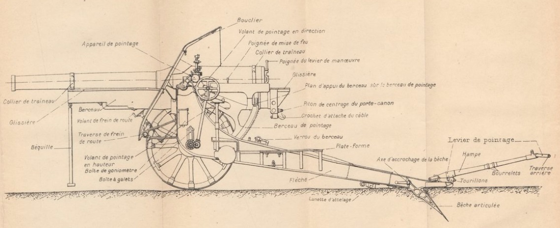
The L14S cradle was fitted with trunnions running in bearings at the top of the front of the trail. As with most French field guns of that era, traversing of the gun was provided by moving the trail sideways by up to 2.25 degrees either side along the wheel axle. A traverse hand wheel was provided on the left-hand side of the trail for this purpose which rotated a traversing screw via an intermediary gear which then moved the trail along the wheel axle which was fitted with teeth for this purpose.

The gun was elevated by means of a pair of large toothed arcs fitted either side under the gun cradle at the rear. A horizontal elevating hand wheel was provided on the left-hand side of the carriage which rotated a pair of elevating arc pinions via a gear train to provide fine adjustment of the gun’s elevation.
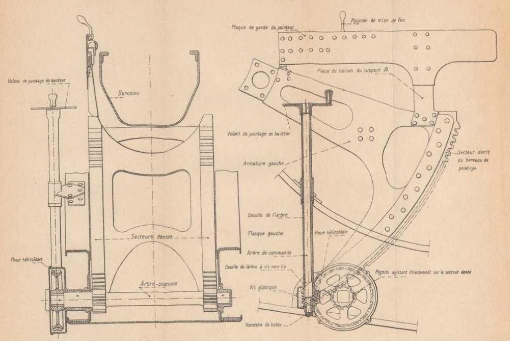
The L14S carriage was also provided with a separate mechanism for rapidly lowering the gun in order to allow easier loading of the shells. The two elevating arcs were actually mounting on the rear of separate brackets that were able to rotate on the gun trunnions. Normally, the rear of these brackets was locked to the gun cradle and therefore raised or lowered the gun when the left-hand hand wheel was used. However, the carriage was also provided with a similar hand wheel on the right-hand side of the cradle that included a lever that allowed the elevating arcs to be unlocked from the cradle. Once unlocked, this hand wheel then operated a pinion engaging with a secondary elevating arc (secteur relevage) that allowed the rear of the cradle to be rapidly raised relative to the main elevating arcs thus lowering the gun. Once the next round had been loaded, the right-hand hand wheel then allowed the gun to be quickly raised again and locked to the elevating arcs.

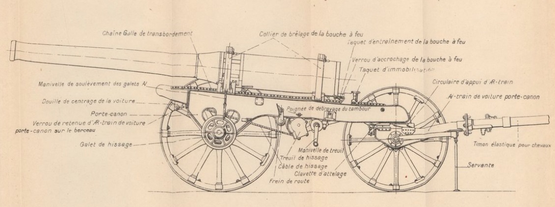
The L14S could either be towed in two separate loads by 8 horse each or as one load by a motor tractor. When horse drawn, the barrel had to be removed and transported on its separate 4-wheel carriage with the gun carriage then towed with the trail supported by a separate 2-wheel bogie. When pulled by a tractor, the gun was normally stowed in the full recoil configuration to even the load on the two pairs of wheels.
 Gun Design
The gun was 4.20 m or 27 calibres long and of built up construction with a jacket shrunk on to the rear third to provide the necessary strength to this part of the gun. The gun was mounted on a sled (traineau) by means of collars at the front and rear and recoiled on the sled within the cradle when the gun was fired.

The Mle 1877 used bagged propellants containing gunpowder pads in the base which were ignited by the flash from a percussion cartridge inserted into the rear of the breech. The problem of sealing the breech was solved by de Bange using an interrupted threaded breech screw with a mushroom shaped obturator projecting from the front of it with a fire proof seal behind the head. When the propellant ignited, the combustion chamber pressure forced the obturator backwards slightly, compressing the seal and forcing it outwards against the rear of the chamber thereby sealing it. The de Bange breech design, in fact, formed the basis for most breech designs that followed using bagged propellants.
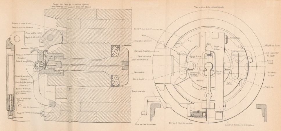
The breech was unlocked by pulling up on the central lever and then rotating the breech plug by 45 degrees after which it could be pulled backwards relative to the hinged bracket and then swung out of the way to the left to expose the breech. The breech plug contained a central vent through which the flash from a percussion cartridge set off the bagged cartridge. The percussion cartridge was fired via a striker hit by a spring loaded hammer (marteau) at the back of the breech which, in turn, was released by operating a trigger (bras de l’axe du marteau) on the left of the breech. This was done remotely using the firing handle (poignee de mise de feu) above the left-hand elevating arc bracket.
Recoil System
Unlike the German and British field howitzers used in WW1 which used hydro-spring recoil systems, the L14S used a much more sophisticated hydro-pneumatic recoil system. This was contained within the cradle (berceau) on a sled (traineau) which recoiled with the gun attached along runners either side of the cradle.
Within the recoil sled, there were two cylinders in the lower part with the right-hand one forming the hydraulic buffer (frein) and the left-hand one forming the recuperator (recuperateur). At the front above these cylinders were 2 reservoirs for the recuperator. The hydraulic buffer is shown at the bottom of the cutaway drawing below which was drawn for clarity with the buffer and the recuperator one above the other rather than side by side.
The hydraulic cylinder was filled with oil and contained a piston on the end of a tube attached to the front of the cradle so that, as the gun recoiled, the cylinder moved backwards while the piston stayed still. The piston contained small ports to restrict the flow of oil past it during recoil and, in so doing, absorbed most of the recoil energy helped a little by the air pressure in the recuperator. The hollow piston tube (tige de frein) was also filled with oil and contained another piston on the end of a rod (contretigre) attached to the rear of the recoil sled. The purpose of this inner hydraulic buffer was to absorb the energy generated by the recuperator in order to bring the gun to a gentle stop when it was returned to battery.

The recuperator is shown just below the large reservoir in the cutaway drawing above and was responsible for returning the gun to battery after the recoil ended. The recuperator consisted of a cylinder in the lower part of the recoil sled, which recoiled with the gun, and a piston on the end of a rod fixed to the front of the cradle. As the cylinder moved backwards, the oil in front of the piston was forced into the two large (grand) reservoirs at the front of the recoil sled thus compressing the air inside. Once the recoil had stopped, this increased air pressure then forced the gun forward back into battery. The ambient air pressure was maintained at 500 psi.
Sights
The sights were mounted on a bracket fixed to the end of the left-hand gun trunnion and therefore elevated with the gun. As for nearly all howitzers, the sights were reciprocating to allow them to compensate for the carriage wheels not being level, which was the norm. Ignoring the spin drift of the shells and the effects of wind, a shell’s trajectory normally lies in the vertical plane through the gun barrel. However, if the wheels and therefore the gun trunnions are not horizontal, this trajectory plane will be rotated away from the centre line of the gun cradle in the direction of the lowest wheel resulting in a large sighting error. To eliminate this effect, the sights were mounted on a reciprocating bracket that could be tilted sideways about an axis parallel to the gun to put the sights back into the same vertical plane as the projectiles. This tilting was performed using the knurled knob (tambour molete de commande) and the cross-level bubble (niveau d’inclinaison) at the rear of the sight.
The required tangent elevation was set on the sight using the large knurled knob at the rear of the sight assembly which controlled the height of a toothed arc on which the sights were mounted- when raised, this tipped the sights forward with a tangent elevation scale provided marked in milliemes (the same as a NATO MIL with 6400 to 360 degrees). A clinometer was provided above the elevation adjustment knob consisting of a level bubble (niveau de site) and a pair of knobs to set the angle of sight from -500 to -500 milliemes . To set the gun to the required quadrant elevation to hit a target at a particular range, the angle of sight and the tangent elevation was set on the sight and then the gun was elevated until the clinometer bubble was level.
The L14S was mainly used for indirect fire where the target was not visible in the sight. A dial sight (goniometre panoramique) was used to set the target direction for the gun in this mode which was basically a copy of the German Goertz sight invented in 1906. This consisted of a panoramic telescope with fixed eye piece and a sighting head that could be rotated up to 360 degrees using the adjustment wheel (plateau mobile) kafway up the sight. In use, one or more aiming points was set up for the gun which could take the form of a prominent feature in the landscape clearly identifiable on a map. The gun plotter then worked out the difference in bearing between a particular gun aiming point and the target which was then set up on the sight using the bearing scale and micrometer adjustment knobs. By aligning the sight on the aiming point, which could be in front of or behind the gun, this ensured that the gun was aligned with the target bearing.
Ammunition
The L14S fired shells weighing approximately 43 kg with a maximum muzzle velocity of 561 m/s and a maximum range of 13,900 m. It used bagged cartridges that could be adjusted to give a number of different sized charges (0, 1, …, 4) with charge 0 being the most powerful. This resulted in different muzzle velocities for the gun depending on the range to the target.
The L14S in common with the other French 155 mm howitzers developed in this era fired either a high explosive (HE) or a Shrapnel shell, all with a nominal weight of 43 kg. These shells were all made of steel. However, in 1915, a shorter cast iron (fonte acieree or FA) shell was produced with a boat tailed design allowing the muzzle velocity to be increased and therefore also the maximum range.
A wide range of fuzes were used with the shells ranging from super quick percussion to dual effect time and percussion.
Canon de 155 L Mle 1877/14 Schneider Specifications
- Length: 7.32 m
- Maximum Width: 1.84 m
- Wheels: Wooden 1.50 m in diameter
- Weight of Gun & Carriage: 5790 kg
- Length of Gun: 4.20 m or 27 calibres
- Bore: 15.5 cm
- Muzzle Velocity: 561 m/s (FA 1915 shell)
- Maximum Range: 13,900 m
- Trail: Box trail
- Recoil System: Hydro-pneumatic
- Maximum Recoil: 1.30 m
- Length of Rifling: 3.171 mm or 20.5 calibres
- Twist: Right-hand with final 1 turn in 25 calibres 1916 onwards
- Grooves: 48
- Firing Method: Percussion
- Elevation: 5° to +42°
- Traverse: -2.25° left to +2.25° right
![]()