

The 15-Pdr BL Gun was the main field gun used by the British Army from about 1892 to 1904 when it was replaced by the 18-Pdr QF Gun that incorporated a modern recoil system. However, the 15-Pdr was too heavy for the Royal Horse Artillery (RHA) in their role of accompanying the cavalry and so they were provided with a lighter version firing a 12-lb shell that was designated the 12-Pdr BL 6 Cwt Gun (the 6 cwt distinguishing it from the pre-1892 12-Pdr BL 7 Cwt gun). In 1904, this lighter gun for the RHA was replaced by the 13-Pdr QF Gun.
The 15-pdr and 12-pdr guns were effectively obsolete by the time of the 2nd Boer War (1899-1902) where they had to face an enemy armed with Creusot and Krupp quick firing (QF) fields guns incorporating modern recoil systems that achieved much higher rates of fire. As a stop gap, the British purchased quick firing (QF) 15-pdr guns from Rheinische Metallwaaren- und Maschinenfabrik AG (now Rheinmetall AG) founded by Heinrich Erhardt that were designated the 15-Pdr QF Gun but are often referred to as Erhardt guns. As well as being used in the Boer War, these guns were also used up to the early part of WW1 by the Territorial Force.
In order to provide the Territorial Force with more guns, many of the 15-Pdr BL guns were converted to add an effective hydro-spring recoil system similar to that fitted to the 18-pdr and 13-pdr guns. However, these were not considered QF guns because they fired bagged cartridges rather than self-contained brass cartridges and so were much slower to load and fire. The converted guns were designated as 15-Pdr BLC (BL Converted) Guns. Nearly all marks of the 15-pdr BL guns were converted resulting in a similar number of marks for the converted guns. It was used by the Territorial Force up to about 1916 when they began to be replaced by 18-pdr guns.

Gun Design
The ordnance (guns) used on the 15-Pdr BLC Guns were basically converted Mk I-IV ordnance from the 15-Pdr BL guns. These guns were 3-inch calibre and 28 calibres long. The Mk I & II guns were of built up construction with a jacket shrunk over the full length of the rifled A-tube. However, the Mk III/IV guns used steel wire wrapped in successive layers over the rear part of the A-tube on to which was shrunk the jacket.
The 15-Pdr BL guns were converted by removing the trunnions from the jacket, plugging the socket holes for the original tangent sights, machining the rear of the jackets to remove the lug for the elevating gear replacing and screwing on a new breech ring with a lug on top for the new recoil system. In addition, bearing rings were shrunk on to the jacket to support the gun in the new cradle during recoil
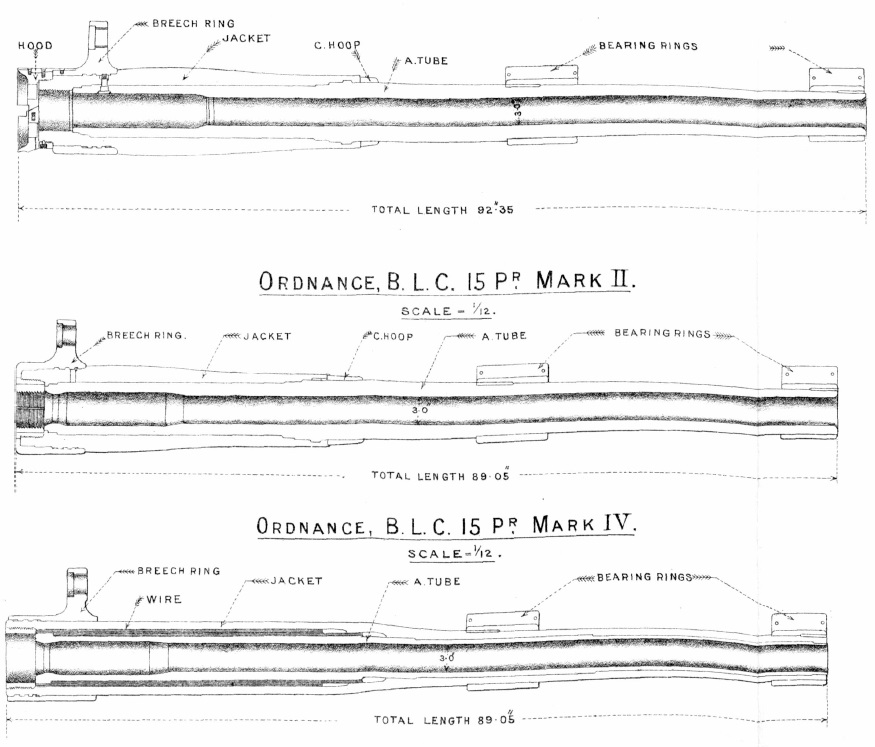
The Mk I/II guns were fitted with a de Bange interrupted breech screw and fired bagged cartridges ignited by a friction T-tube placed in a radial vent in the side of the chamber. These used a ‘Three Motion Breech Mechanism’: step one, lift the operating lever; step two, rotate the breech screw with the lever through 60; step three, withdraw the breech screw in its carrier and then swing it to the right out of the way.
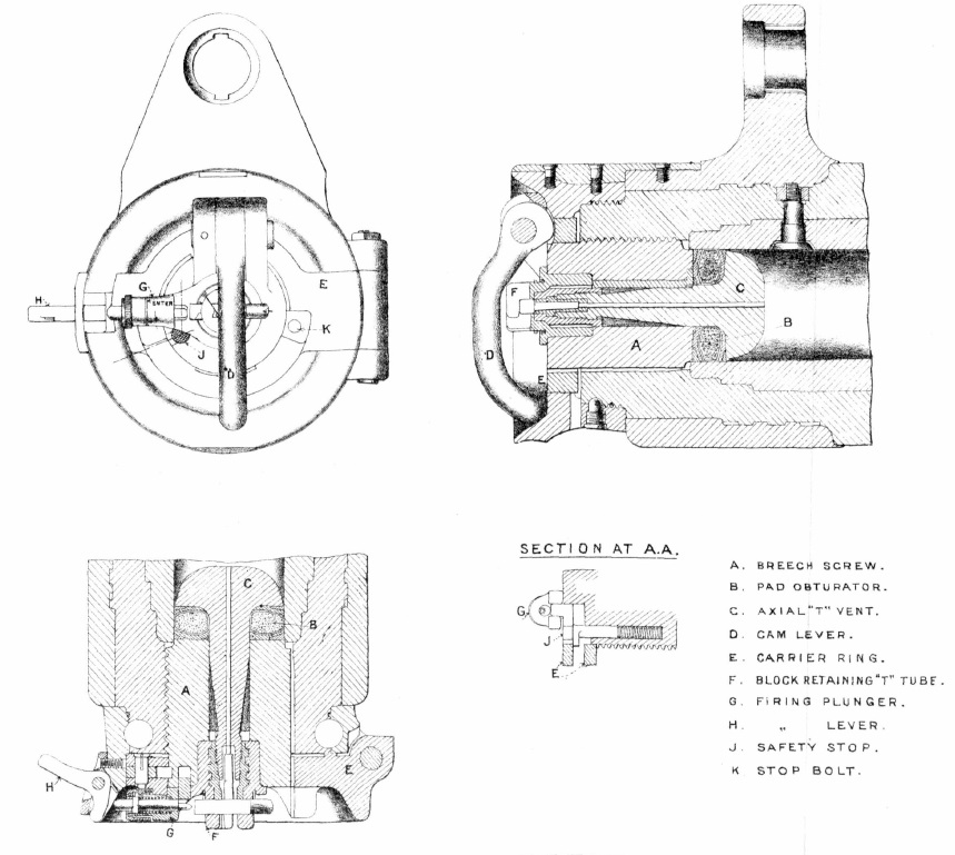
The later marks of the gun used a parallel screw Welin breech that employed a much stronger stepped thread than the de Bange breech screw. It was operated by a ‘Single Motion Breech Mechanism’. Pulling the lever, rotated the breech screw and then withdrew it clear of the breech. The gun was fired using a friction T-tube inserted into the centre of the breech screw firing through an axial vent to ignite the bagged cartridge in the chamber.

Carriage Design
The trail consisted of two side brackets connected by transoms and was fitted with an axletree mounting two 5 foot wooden spoked wheels with 3 inch steel tyres. The trail also provided the bearings for the cradle trunnions. The carriage was fitted with a shield with a fixed upper part and a hinged lower section that could be removed. It was fitted with a spade at the rear that allowed the end of the trail to be traversed relative to the spade by up to 2° to the left or right using the handspike. If more than 2° of traverse was required, the spade had to be lifted and then moved sideways.

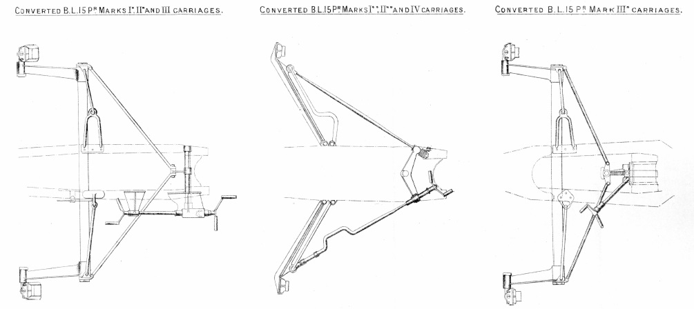
Brake shoes were fitted that acted against the rear of each wheel whose operating mechanism depended on what mark of 15 Pdr BL gun carriage was converted. The earlier marks used brake shoes mounted on arms at the end of a cross-shaft while the later marks used brake shoes on the ends of arms that pivoted off the side of the carriage. The brakes were operated by a handle(s) whose location depended on the mark of the converted gun as shown below.
As in the 15-Pdr BL guns, the 15-Pdr BLC guns were elevated using an elevating screw under the rear of the cradle that was supported on an oscillating bracket between the trail frames. The elevating screw was operated via gears by a hand wheel on the left of the trail. Both the gun loader on the right and the gun layer on the left were provided with adjustable seats. Unlike the 15-Pdr BL guns that recoiled violently backwards during firing requiring the detachment members to stand well clear, this was not required by the converted guns who could stay seated at their posts while the gun fired.

Limbers
The gun was towed behind a two wheel limber pulled by 6 horses with a wooden ammunition box on top. The gun was also accompanied by an ammunition wagon mounting an ammunition box that was pulled by a similar limber and 6 horses. A range of different marks od limber and ammunition wagon were used.
In Mk I form, the limber ammunition box held 38 shrapnel shells, 2 case shot, 40 cartridges, 40 fuzes, 50 friction T-tubes together with other accessories. The shells were stored vertically. The ammunition box on the ammunition wagon held the same number shells, fuses and friction T-tubes. In both cases, the shrapnel shells were stored on removable wooden carriers each containing 4 shells and 4 cartridges.
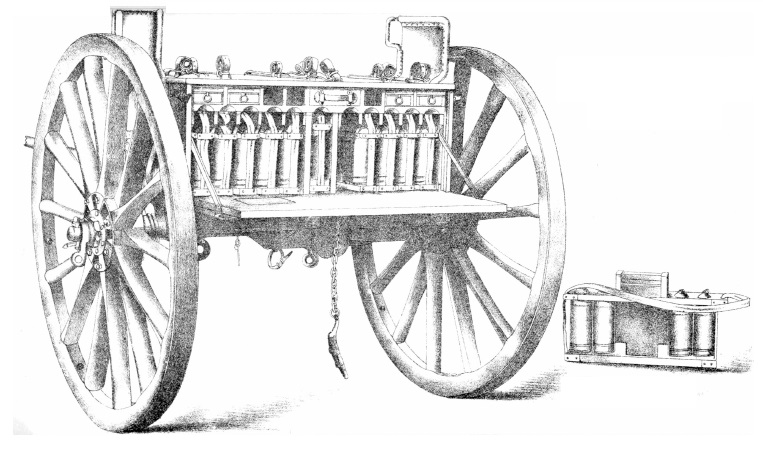
However, the 15-Pdr BLC Gun also used Mk Ib and Ic limbers and ammunition wagons. In Mk Ic form, the limber ammunition box and ammunition wagon held 46 shrapnel shells, 40 cartridges , 2 case shot together with fuzes, friction T-tubes other stores.

Recoil System
The recoil system for the 15-Pdr BLC gun was basically the hydro-spring system from the 13/18-pdr. It consisted of an outer spring case that was fixed to the cradle. Within the outer case was an outer spring supported on the outside of the inner spring case. Inside the inner spring case was the inner spring and within that the hydraulic buffer.
The hydraulic buffer consisted of a cylinder that was attached at the rear to a lug on top of the breech ring. The buffer was filled with oil and contained a piston on the end of a rod that was bolted to the front of the outer spring case. As the gun recoiled, the buffer cylinder was pulled backwards and oil had to flow past the piston from the front of the cylinder to the rear. It did this via grooves machined into the inner surface of the cylinder with the restricted oil flow creating the damping force required to absorb the recoil of the gun.
As the buffer cylinder recoiled backwards, a flange on the front of it pressed against the front end of the inner spring compressing it against the rear of the inner spring case. This in turn forced the inner spring case to move backwards and caused the flange on the front of it to press against the outer spring compressing it against the rear of the outer spring case. Thus, when the gun recoiled, the hydraulic cylinder and the inner spring case both telescoped backwards out of the outer spring case. The maximum recoil of the gun was 40 inches.
When the recoil ended, the springs pushed the gun back into battery. However, towards the end of the forward movement, a control rod at the rear of the buffer cylinder entered the hollow piston rod that was filled with oil. Forcing the oil out through small holes dampened the final stages of movement and brought the run out to a smooth end.

Sights
The 15-Pdr BLC Gun was fitted with a rocking bar sight with the sight bar supporting a No. 6 sighting telescope at the rear with open sights also fitted consisting of an acorn post foresight and a notched leaf rear sight. The leaf was fitted with a deflection screw that provided up to 2.25° of deflection to the left or right.
The sight bar was supported at the front on a ball and socket attached to a cradle bracket. It was supported at the back via a cradle brake that allowed it to tilt sideways on a pivot pin to allow the sight to be levelled to compensate for the wheels not being level as was the norm. The reciprocating bracket was provided with a levelling screw and a cross bubble for this purpose. To compensate for drift, the cross level was tilted at 1.5°.
The rear end of the sight bar was supported on a toothed arc was that was raised or lowered by a worm gear rotated by the range drum. The range drum was graduated up to 6,100 yds in intervals of 25 yds. The No. 6 telescope was fitted with a longitudinal level with a micrometer adjustment for setting the angle of sight. For greater accuracy in indirect fire mode, the field clinometer could be used on the plane provided on the top of the breech to set the gun’s quadrant elevation.
When used for indirect fire, the required angle of sight and range were set on the sight and then the gun was elevated to centre the bubble in the longitudinal level . Laying for line was achieved using the No. 1 dial sight shown below that was mounted on the top of the gun shield. The dial sight consisted of a circular carrying plate marked with degrees on the outside on top of which was a sight plate carrying the aiming arm with acorn post at the front and a notch at the rear. The carrying plate was adjusted on its support bracket so that it was level before use. In indirect fire, the gun was layed for line using either an aiming point that could be seen in the landscape surrounding the gun or using aiming posts set up near the gun. The required target direction was defined relative to the gun’s aiming points or posts and set up on the dial sight. By traversing the gun until the aiming point or post was centred in the dial sight then ensured the gun was pointing precisely in the specified target direction.

Crew Detachment
The 15-Pdr BLC Gun was operated by a detachment of 10 men when first introduced into service whose duties were:
No. 1: The senior NCO commanding the detachment who checked that the time fuzes had been correctly set, rammed home the shell and cartridge, and was responsible for using the traversing handspike.
No. 2: Sat in right-hand seat and attended to the breech mechanism and brake.
No. 3 : Sat in left-hand seat and layed the gun in direction and elevation and fired the gun.
No. 4: Loaded the ammunition into the breech, planted the aiming posts and adjusted their position.
No. 5: Issued ammunition and set the fuzes.
No. 6: Set the corrector calling out the length of the fuze and assisted No. 5.
No. 7, 8 and 9 were reserve men and only came to the firing line to replace casualties. Normally, the detachment worked on their own side of the carriage, even numbers on the right and odd numbers on the left.
When travelling, the No. 1 and 10 rode on their horses stationed to the left of the front horse in the carriage and ammunition wagon limbers, respectively. The Nos. 2 & 3 rode on the gun limber, the Nos. 4 & 5 rode on the ammunition wagon limber, No. 6 rode on the body of the firing battery wagon, and Nos. 7 & 8 rode on the limber of the first line wagon, and No. 9 rode on the body of the first line wagon.
Ammunition
The 15-Pdr BL gun fired bagged charges. These were made of red shalloon about 11.5 inches long and contained approximately 16 oz of Cordite. Two drams of gun cotton yarn were wound around the bundles at each end to be ignited when the friction T-tube was fired. The T-tube contained gun powder that was ignited by friction when the loop was pulled out via a lanyard with the resulting flash travelling down the the T-vent in the breech screw to ignite the bagged charge.
The 15-Pdr BLC was designed to fire only shrapnel shells and case shot. The Mk VI shrapnel shell weighed 14 lb and was 9.0 inches long. It was filled with 230 mixed metal balls supported on a cup of sheet iron at the base that contained the bursting charge. This was set off by the flash from the time & percussion fuze travelling down the central tube.
The case shot was essentially a cylindrical tin case 9 inches long filled with 290 mixed metal balls. When the propellant charge was fired, this effectively blew the metal balls out of the front of the canister to spray the ground up to several hundred yards in front of the gun.
The shrapnel shells were originally fitted with a No. 56 time and  percussion fuze that was graduated from 0 to 18 but burned for a maximum of 13 seconds limiting the maximum range for a shrapnel air burst to just over 4,000 yards. The fuze was fitted with two safety pins attached to string loops, one for the percussion function and one for the time function with the time loop being scarlet. To select which function was to be used, the appropriate pin had to be withdrawn before the round was fired. Eventually, the No. 56 fuze was replaced by the generally similar No. 60 fuze that was graduated from 0 to 44 and burned for a maximum of 20 seconds extending the range of the shrapnel shells to 6,000 yards.
15-Pdr BLC Gun Specifications
- Length: 12 ft 7 in
- Wheel Track: 5 ft 2 in
- Wheels: 5 ft
- Weight of Gun & Carriage: 26 cwt 1 qr 13 lb MkI: 25 cwt 0 qr 7 lb Mk II: 24 cwt 2 qr 15 lb Mk IV
- Weight of Carriage & Limber: 43 cwt 0 qr 13 lb MkI: 41 cwt 1 qr 7 lb Mk II: 42 cwt 0 qr 15 lb Mk IV
- Calibre: 3 in
- Length of Bore: 84 in (28 calibres)
- Weight of Gun & Breech: 8 cwt
- Muzzle Velocity: 1574 fps
- Maximum Range: 6000 yd
- Trail: Box section
- Recoil System: Hydro-spring
- Maximum Recoil: 40 inches
- Rifling: Polygroove with hook section
- Length of Rifling: 71.6 in
- Twist: 1 turn in 120 cal to 1 turn in 28 cal 35.8 in from breech
- Grooves: 18
- Firing Method: Friction T-Tube
- Elevation: -9° to +16° Mk I: -5.5° to +15.5° Mk II:-9° to +15.5° Mk II/IV:
- Traverse: 2° to left or right using spade traversing mechanism
![]()