

At the start of WW1, France had over 1300 obsolete Canon de 155 L Mle 1877 de Bange heavy field guns in its inventory which were built before the advent of effective recoil systems. In the early years of the war, 120 of these were modernised by Schneider using the carriage from the Canon de 105 L Mle 1913 Schneider and were designated as the Canon de 155 L Mle 1877/14 Schneider. The main disadvantage of this conversion was its weight which required the guns to be transported separately from the carriage. In order to produce a more mobile conversion, Schneider proposed mating the de Bange guns with the carriage developed for the Canon de 155 C Mle 1917 Schneider or C18S The new conversion was designated the Canon de 155 Mle 1918 Schneider or the L18S. Again, 120 conversions were ordered but only 4 were delivered before the end of the war with the rest delivered in 1919 and 1920.
Carriage
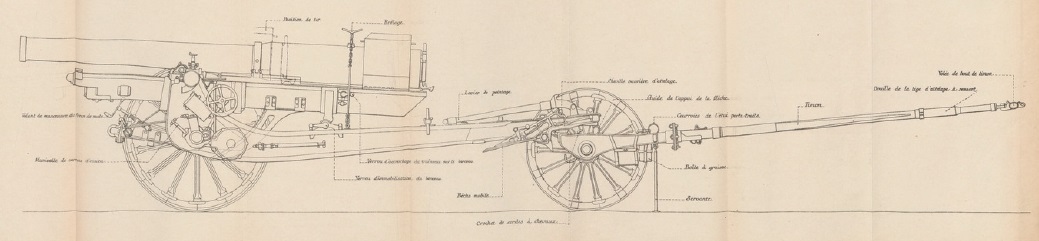
The L18S carriage consisted of a box trail with side arms in the front half that allowed space for the gun to recoil at higher elevation angles. Unlike the carriage of the C17S, the carriage of the L18S was not fitted with a gun shield. The rear of the trail was provided with a spade to stabilise the gun during firing which was supplemented by brake shoes acting on the front of the steel tyres on the wooden wheels which were fixed to the end of a steel axle passing through the trail. Compared with the original Mle 1877 gun, the trunnions were further back and therefore to balance the gun a large counter weight was bolted on the top of the breech.
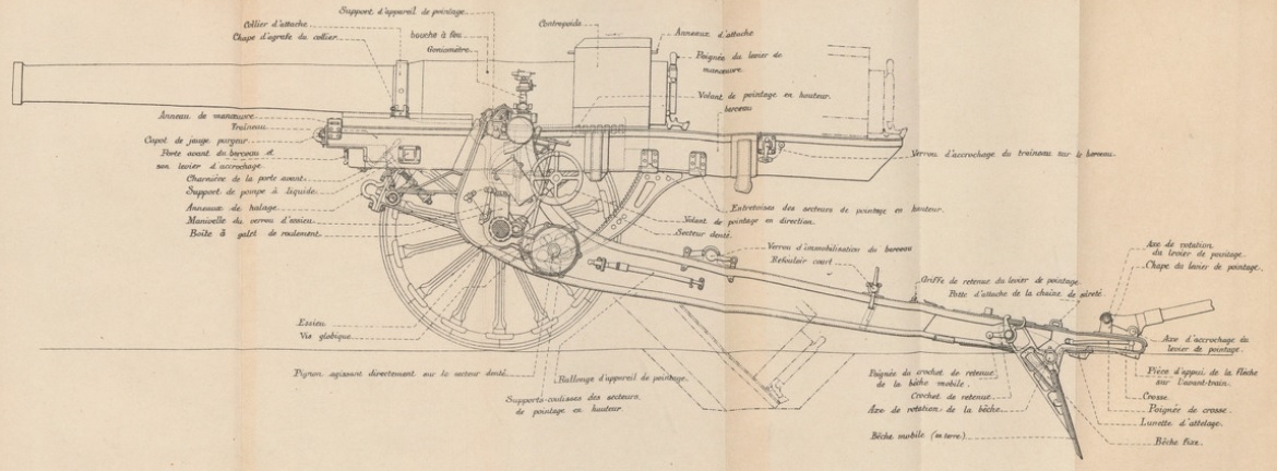

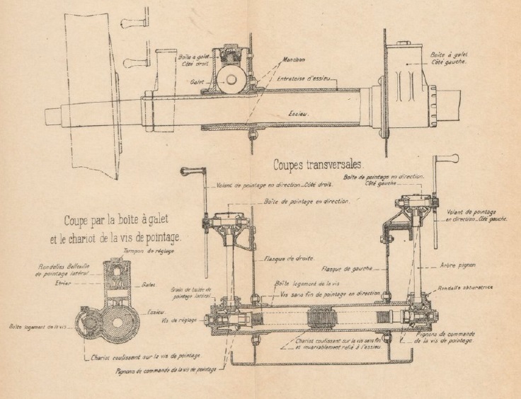
The gun pivoted on trunnions running in bearings at the top of the front of the trail with traverse provided by moving the trail sideways by up to 3 deg either side along the wheel axle. A traverse hand wheel was provided on both sides of the trail for this purpose which rotated a traversing screw via bevel gears which then moved the trail along the wheel axle which was fitted with teeth for this purpose.
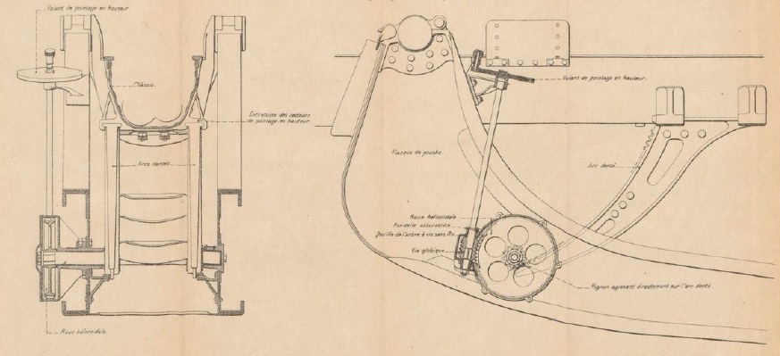
The gun was elevated by means of a pair of large toothed arcs fitted either side under the gun cradle. An elevating hand wheel was provided on the left-hand side of the carriage which rotated a pair of elevating arc pinions via a gear train to provide fine adjustment of the gun’s elevation. The maximum elevation was 43° 35′.
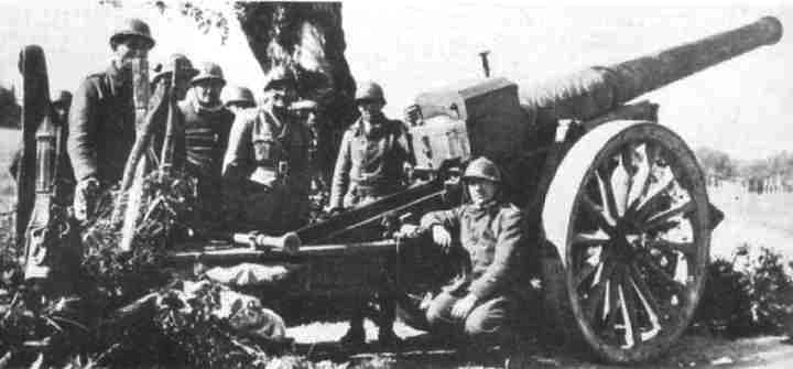
The gun was transported by either 10 horses or via motorised tractor with the gun hooked up to a two wheel limber as shown. In order to balance the gun between the two sets of wheel, it was locked in the full recoil position.
Gun Design
The gun was 4.09 m or 26.4 calibres long and of built up construction with a jacket shrunk on to the rear third to provide the necessary strength to this part of the gun. The gun was mounted on a sled (traineau) by means of collars at the front and rear and recoiled on the sled within the cradle when the gun was fired.

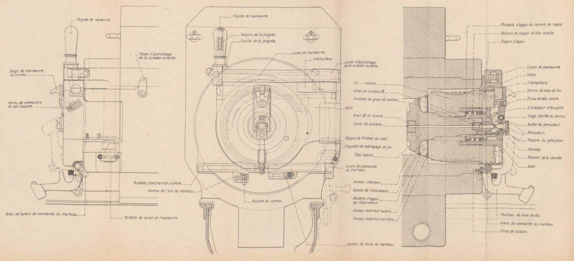
The original Mle 1877 gun used a de Bange breech but the L18S used the same breech as the L17S. It used an interrupted screw breech with a single motion lever that, when operated, rotated the breech screw to unlock it before swinging it clear of the breech opening. The sealing of the breech (obturation) was achieved by using a mushroom shaped obturator that fitted into the front of the breech block. Between the mushroom head and the front of the breech block was a sealing ring such that, when the breech was closed, the seal was pressed against the tapered rear of the combustion chamber. When a charge was fired, the combustion chamber pressure pushed the obturator slightly backwards further compressing the sealing ring against the side of the chamber completely sealing it.
The C18S used bagged charges which were ignited using a percussion cartridge that fired through a vent in the centre of the obturator. This cartridge was set off by a striker that was hit by a hammer (marteau) at the rear of the breech that was cocked manually and released via a lanyard.
Recoil System
Unlike the German and British field howitzers used in WW1 which used hydro-spring recoil systems, the L18S used a much more sophisticated hydro-pneumatic recoil system. This was contained within the cradle (berceau) on a sled (traineau) that recoiled with the gun attached along runners either side of the cradle.
Within the recoil sled, there were two cylinders in the lower part with the left-hand one forming the hydraulic buffer (frein) and the right-hand one forming the recuperator (recuperateur). At the front above these cylinders were 2 reservoirs for the recuperator. The hydraulic buffer is shown at the bottom of the cutaway drawing below which was drawn for clarity with the buffer and the recuperator one above the other rather than side by side.
The hydraulic cylinder was filled with oil and contained a piston on the end of a hollow rod attached to the front of the cradle so that, as the gun recoiled, the cylinder moved backwards while the piston stayed still. The piston contained small ports to restrict the flow of oil past it during recoil and, in so doing, absorbed most of the recoil energy helped a little by the air pressure in the recuperator. The hollow piston tube (tige de frein) was also filled with oil and contained another piston on the end of a rod (contretigre) attached to the rear of the recoil sled. The purpose of this inner hydraulic buffer was to absorb the energy generated by the recuperator in order to bring the gun to a gentle stop when it was returned to battery.

The recuperator is shown just below the large reservoir in the cutaway drawing above and was responsible for returning the gun to battery after the recoil ended. The recuperator consisted of a cylinder in the lower part of the recoil sled, which recoiled with the gun, and a piston on the end of a rod fixed to the front of the cradle. As the cylinder moved backwards, the oil in front of the piston was forced into the two large (grand) reservoirs at the front of the recoil sled thus compressing the air inside. Once the recoil had stopped, this increased air pressure then forced the gun forward back into battery. The ambient air pressure was maintained at 500 psi.
Sights
The sights were mounted on a bracket fixed to the end of the left-hand gun trunnion and therefore elevated with the gun. As for nearly all howitzers, the sights were reciprocating to allow them to compensate for the carriage wheels not being level, which was the norm. Ignoring the spin drift of the shells and the effects of wind, a shell’s trajectory normally lies in the vertical plane through the gun barrel. However, if the wheels and therefore the gun trunnions are not horizontal, this trajectory plane will be rotated away from the centre line of the gun cradle in the direction of the lowest wheel resulting in a large sighting error. To eliminate this effect, the sights were mounted on a reciprocating bracket that could be tilted sideways about an axis parallel to the gun to put the sights back into the same vertical plane as the projectiles. This tilting was performed using the knurled knob (tambour molete de commande) and the cross-level bubble (niveau d’inclinaison) at the rear of the sight.
The required tangent elevation was set on the sight using the large knurled knob at the rear of the sight assembly which controlled the height of a toothed arc on which the sights were mounted- when raised, this tipped the sights forward with a tangent elevation scale provided marked in milliemes (the same as a NATO MIL with 6400 to 360 degrees). A clinometer was provided above the elevation adjustment knob consisting of a level bubble (niveau de site) and a pair of knobs to set the angle of sight from -500 to -500 milliemes . To set the gun to the required quadrant elevation to hit a target at a particular range, the angle of sight and the tangent elevation was set on the sight and then the gun was elevated until the clinometer bubble was level.
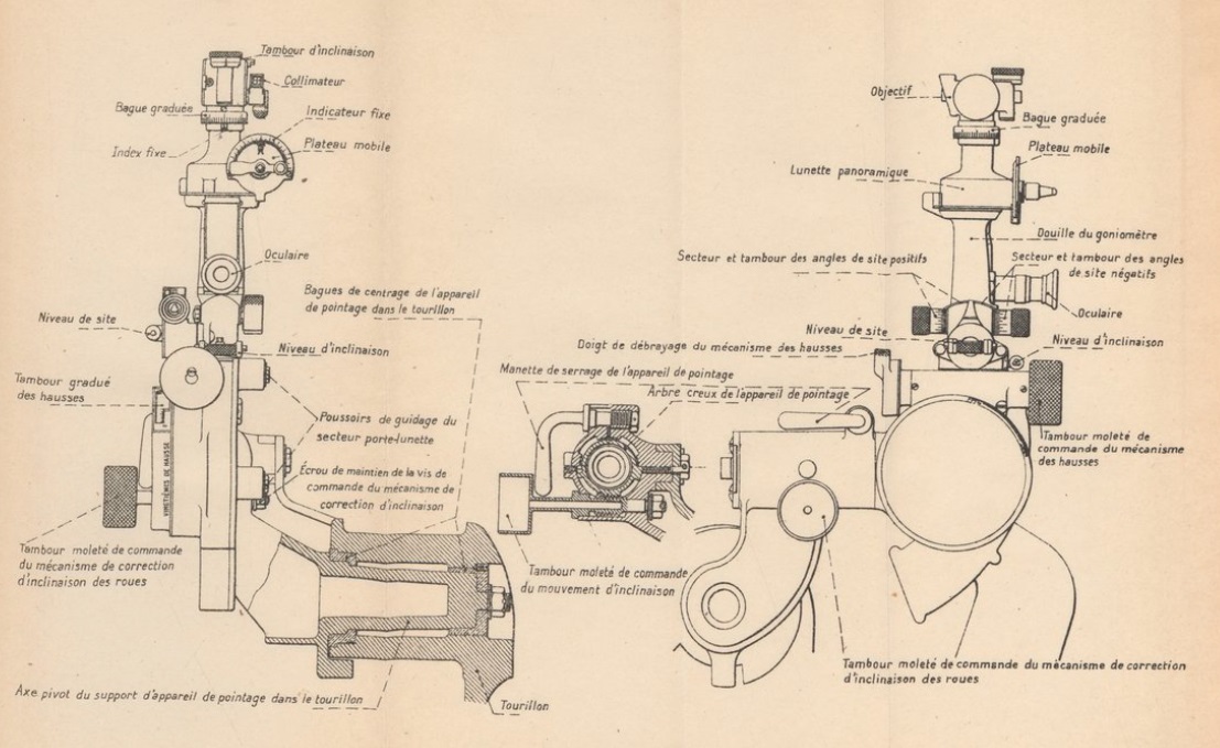
The L14S was mainly used for indirect fire where the target was not visible in the sight. A dial sight (goniometre panoramique) was used to set the target direction for the gun in this mode which was basically a copy of the German Goertz sight invented in 1906. This consisted of a panoramic telescope with fixed eye piece and a sighting head that could be rotated up to 360 degrees using the adjustment wheel (plateau mobile) halfway up the sight. In use, one or more aiming points was set up for the gun which could take the form of a prominent feature in the landscape clearly identifiable on a map. The gun plotter then worked out the difference in bearing between a particular gun aiming point and the target which was then set up on the sight using the bearing scale and micrometer adjustment knobs. By aligning the sight on the aiming point, which could be in front of or behind the gun, this ensured that the gun was aligned with the target bearing.
Ammunition
The L18S used bagged cartridges with an igniter pad sown into the base which was ignited by the flash from the percussion cartridge at the back of the breech vent. Several different sized charges were used (0, 1 & 2) giving different muzzle velocities with Charge 0 being the most powerful.

The L18S fired shells nominally weighing 43 kg and were mainly high explosive filled. However, smoke and gas shells were also fired. The earlier shells were made of steel (acier) but the Mle 1915 and 1918 shells were made from cast iron (fonte acier) and, with a more streamlined shape, gave a great muzzle velocity and range.

A wide range of fuzes were used with the shells ranging from super quick percussion to dual effect time and percussion.

Canon de 155 L Mle 1918 Schneider Specifications
- Length: 7.09 m
- Maximum Width: 1.95 m
- Wheels: Wooden 1.50 m in diameter
- Weight of Gun & Carriage: 5050 kg
- Length of Gun: 4.09 m or 26.4 calibres
- Bore: 15.5 cm
- Muzzle Velocity: 561 m/s (FA 1915 shell)
- Maximum Range: 13,600 m
- Trail: Box trail
- Recoil System: Hydro-pneumatic
- Maximum Recoil: 1.40 m
- Rifling: Progressive 1 turn in 25 calibres to 1 turn in 13.6 calibres
- Length of Rifling: 3.171 m or 20.5 calibres
- Grooves: 48
- Firing Method: Percussion
- Elevation: 1° 15′ to +43° 35′
- Traverse: -3° left to +3° right
![]()