

The 10 cm Kanone 14 (K14) was introduced into service in 1915 and was intended to be dual role: to be both a long range field gun firing high explosive shells and also as an anti-aircraft gun. To fulfil the latter role in particular, the K14 was equipped with 2-man laying with the gun layer responsible for keeping the sights aimed at the target but with the right-hand crew member responsible for adjusting the range. The K14 was not successful as an anti-aircraft gun as the 2-man laying system proved difficult to use effectively.
However, the K14 was successful as a long range field gun. In order to increase the maximum range still further, a modified version of the K14 was introduced in 1917 as the 10 cm Kanone 17 (K17) with the barrel length increased from 35 to 45 calibres. Most of the features of the K14 were retained with the main changes being the elimination of the semi-automatic sliding horizontal breech and the move of the range drum from the right to the left-hand side of the carriage. Surprisingly, the complicated elevating mechanism was retained as was the variable recoil system making the K17 just as difficult to manufacture as the K14.
However, in parallel, a simplified version of the K17 was introduced as the K17/04 that eliminated the complex elevating mechanism in favour of a more conventional one with a single hand wheel for the gun layer. The complicated sights on the K17 were also changed to a conventional set of sights similar to that on the 15 cm schwere Feldhaubitze 13.

Carriage
The K17 used a similar carriage to the K14. It consisted of a box trail with side arms to provide space for the gun to recoil downwards. It was fitted with a splinter shield and a spade and a deployable traversing pole at the rear . The carriage was mounted on wooden wheels with steel tyres. Brake pads were provided in front of the wheels to help stabilise the gun during firing operated by a lever on the right side just above the wheel axle. A seat was provided for the gun layer on the left of the carriage.
The gun was mounted on a cradle containing the hydro-spring recoil system and was fitted with rear mounted trunnions to minimise the change in height of the breech as the gun was elevated. The cradle trunnions were supported in bearings at the top of the saddle on either side which had triangular side walls. The saddle pivoted in the horizontal plane on a bearing at the front of the trail allowing the gun to be traversed by up to 3 degs either side via a screw jack on the left-hand side of the trail operated by a hand wheel. The gun was elevated via a horizontal pinion shaft and two elevating arcs under the cradle behind the shield. To support the unbalanced weight of the gun and cradle, a spring equilibrator was mounted under the cradle between the two elevating arcs.

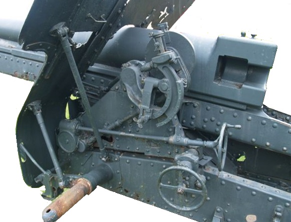
The K17 used two-man laying in the same way as the K14. The gun layer operated the two hand wheels on his side of the cradle to traverse the gun and to elevate the gun to set the angle of sight on the gun; that is, the angle of the target above the horizontal plane through the gun. The right-hand crew member was provided with a separate hand wheel on the right-hand side of the cradle which he used to elevate the gun to give the required range. The complicated elevating mechanism was achieved using a planetary gearbox on the right-hand side of the saddle and a worm wheel gearbox on the left-hand side, with a drive shaft needed between the former and the range drum. More details can be found in the description of the K14.
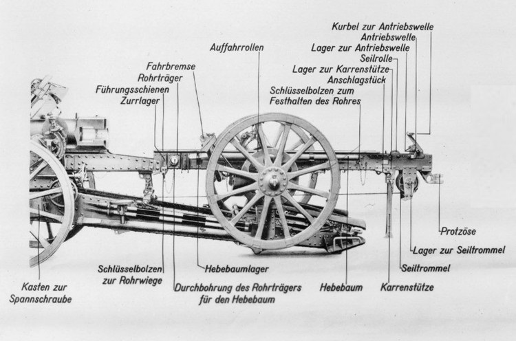
The K14 was transported as one load by a team of size horses. However, the K17 was too heavy for this because of the extra weight of the longer gun barrel and so had to be transported as two loads. As shown below, a special transport carriage with a built in winch was used that allowed the gun to be pulled on to it. This was facilitated by the two ramps fitted to the back of the K17 trail allowing the transport carriage to be wheeled on to the back of it.
Gun Design
The gun was 4.73 m or 45 calibres long with the rifled part of the barrel being 37 calibres or 3.89 m in length. The gun was of built up construction with a jacket shrunk on to the rifled tube and extending for about half the length of the barrel. Brackets were provided on the jacket and breech to support guides that allowed the gun to recoil along the top of the cradle
The jacket was shaped at the rear to support a horizontal sliding breech block of Krupp design that opened to the right. It was opened by a lever on the right-hand side of the breech which automatically ejected any empty cartridge. The breech incorporated an axial striker to fire a loaded cartridge which was fired using a lanyard fitted to the trigger arm on the right-hand side of the breech.
Recoil System
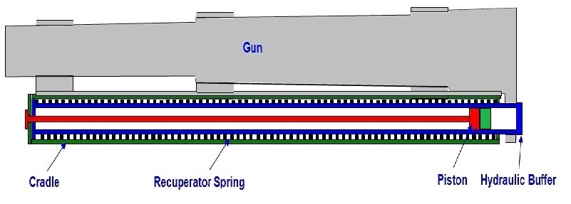
The K17 used a hydro-spring recoil system mounted within the cradle. This consisted of a oil filled hydraulic buffer whose cylinder was connected to a lug under the breech with a coaxial spring mounted on the cylinder to form the recuperator. The hydraulic piston was fixed to the end of a rod attached to the front of the cradle.
As the gun recoiled and the hydraulic cylinder was pulled backwards, the oil was forced to flow through the piston resisting its movement and absorbing the energy of recoil. The piston was fitted with ports for this purpose but was also fitted with a rotating valve with a similar set of ports. The rotating valve was keyed into a pair of spiral grooves in the surface of the hydraulic cylinder that caused it to rotate when the gun recoiled. At the start of recoil, both sets of ports were aligned to provide maximum oil flow rate but, as the gun recoiled and the rotating valve rotated, a point was reached where the sets of ports were no longer aligned and the flow of oil was stopped bringing the recoil to an end. At the same time that the hydraulic cylinder recoiled backwards, it compressed the large coaxial spring so that, once the recoil had been brought to an end, the spring forced the gun back into battery.
Even using rear mounted gun trunnions that limited the height movement of the breech, the recoil length had to be shortened as the gun was elevated in order to stop the breech hitting the ground. The K17 therefore used a variable recoil mechanism. The length of recoil was varied by rotating the piston rod as a function of the gun’s elevation angle to change the cut off point for oil passing through the piston and rotating valve. In the K17, the front end of the piston rod was fitted with a pinion that engaged with a toothed arm on the end of a control rod mounted inside the cradle. The control rod was rotated by a mechanism near the left gun trunnion as the gun was elevated which in turn rotated the piston rod and shortened the length of recoil. The recoil length varied between 1.55 m to 0.95 m at max elevation.
Sights
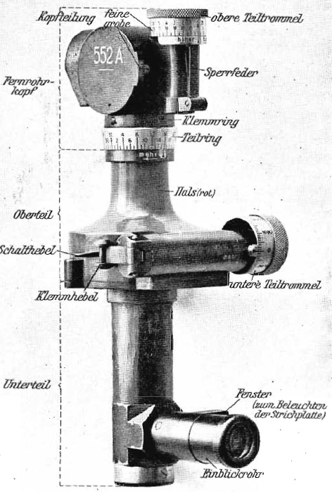
The basic sighting device used on the K17 was a dial sight or panoramic telescope (Rundblickfernrohr) that was invented by Goertz in 1906. The sights were reciprocating to allow them to compensate for the wheels and, therefore, the trunnions not being level which was the norm. If uncorrected, this would lead to the sights not being in the same vertical plane as the gun barrel since this would be rotated away from the centre line of the carriage in the direction of the lowest wheel leading to a large sighting error especially at higher elevation angles.
The sights were bolted via a sight bracket to the left-hand trunnion and so elevated with the gun. The sights themselves were mounted on a reciprocating bracket that could be tilted sideways on the sight bracket about an axis parallel to the gun barrel. In practice, the reciprocating bracket was tilted sideways using the butterfly knob provided until the cross-bubble on the dial sight bracket was levelled putting the sights back into the same vertical plane as the gun barrel.
As with most German field guns of this era, the dial sight was mounted on a bracket on the end of a toothed sight arc that moved within the reciprocating bracket. When raised or lowered, this would tilt the sight forward or backwards to change the elevation angle of the sight. On the K14, the range drum was on the right of the gun and driven from a drive rod straight from the ring gear in the planetary gearbox that was rotated via the right-hand elevating hand wheel. An extension of the drive across the top of the gun raised or lowered the toothed sight arc. Both the range drum and the sight arc displayed the tangent elevation set by the right-hand crew member. A similar arrangement was incorporated on the K17 except the range drum was moved to the left-hand side and housed on the sight assembly and the drive from the planetary gearbox passed underneath the gun via the worm gearbox on the left.
The K17 was designed to provide indirect fire only with the required quadrant elevation and relative bearing for the target passed to the gun crew. The right-hand crew member elevated the gun until the required quadrant elevation or range was indicated on the range dial which he must have been able to read from his side of the gun. The gun layer would then have used his elevating hand wheel to change the elevation of the gun until the longitudinal bubble on the sight clinometer incorporated into the dial sight bracket was level.
The required target bearing was specified relative to an aiming point set up for the gun that could be seen in the dial sight – this could be a prominent feature in the landscape or it could be sighting rods specially set up some distance from the gun. The Goertz sight had a fixed eyepiece but the sighting head at the top could be rotated through 360 deg using the micrometer knob provided. A graduated ring was provide to indicate the angle of rotation. The relative bearing for the target was set on the dial sight and then the gun traversed until the aiming point was centred in the sight which meant the gun was then aligned with the required target bearing.
 Ammunition
The K17 fired fixed ammunition comprising of the shell with the brass cartridge case attached. The case included a primer in the base that was struck by a striker to fire the projectile.
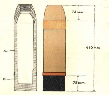 The K17 fired the 10 cm Gr. 15 shell which had a length of 410 mm and was filled with a bursting charge of 1.8 kg of Picric Acid. It had a nominal weight of 18 kg. It was fitted with a Gr. Z. 04 percussion fuze or a Dopp. Z. 15 triple action fuze that could be used as a time fuze or a percussion fuze with or without a delay.
10 cm Kanone 17 Specifications
-
- Length: 7.93 m
- Maximum Width: 1.86 m
- Wheels: Wooden 1.53 m in diameter
- Weight of Gun & Carriage: 3357 kg
- Length of Gun: 4.73m or 45 calibres
- Bore: 10.52 cm
- Muzzle Velocity: 650 m/s
- Maximum Range: 14,100 m
- Trail: Box trail
- Recoil System: Hydro-spring
- Maximum Recoil: Variable 1.55 m to 0.95 m at max elevation
- Rifling: Polygroove with modified plain section
- Length of Rifling: 37 calibres (3.89 m)
- Twist: Progressive with 1 turn in 45 to 1 turn in 25 calibres
- Grooves: 32
- Firing Method: Percussion
- Elevation: -2° to +45°
- Traverse: -3° left to +3° right
![]()