

In 1909, Rheinmetall and Krupp were both asked by the German APK (Artillerie Prüfungs Kommission – artillery testing commission) to develop a new 15 cm howitzer with a longer barrel to increase the range compared with the 15 cm schwere Feldhaubitze (sFH) 02 introduced in 1902 and also incorporating a splinter shield for the crew. Another key requirements was that the gun was light enough to be towed by a team of 6 horses as one load. Experimental guns from both companies were produced and tested and, although the Rheinmetall gun had a more advanced variable recoil system, it was of shorter range and heavier than the Krupp gun. As a result of this, the Krupp gun was selected for production in 1913 as the 15 cm sFH 13.
The sFH 13 served throughout WW1 with the original gun being 14 calibres in length using a hydro-spring recoil system. However, in the early part of WW1, as a result of heavy use, it was found that the recuperator springs regularly broke not unlike the problem found with the British Ordnance QF 18-Pdr. A similar solution was found by changing to a hydro-pneumatic recoil system in 1915.
Another problem experienced with the sFH 13 were ruptured barrels due to the larger propellant charges needed to increase the range of the gun. A number of changes were therefore made to eliminate this problem including an increase in barrel length to 17 calibres to produce the lange (lg or long) sFH 13 version. Other changes made were to the chamber shape to reduce the maximum pressure generated during firing and a change in the pitch of the rifling.
Later in the war, a simplified version of the lg sFH 13 was produced which was designated the 15 cm lg sFH 13/02. In this version, the folding splinter shield was changed to a fixed shield, the hydro-pneumatic recoil system was changed back to a hydro-spring system to ease manufacturing difficulties, the loading handle for the gun was eliminated and the seats for the gun layer and loader were removed.
 Carriage
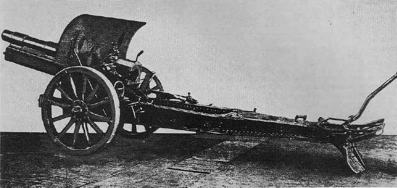
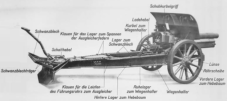
The sFH 13 used a box trail fitted with side arms towards the front to provide space for the gun to recoil downwards. It was fitted with a splinter shield whose upper part could be folded down during transporting and was fitted with a deployable spade at the rear with a recoil plate (schwanzblech) provided that could be fixed above the spade to stop the rear of the trail digging in too deeply during firing. The carriage was fitted with wooden wheels and steel tyres. Brake pads were provided in front of the wheels to help stabilise the gun during firing operated by a lever on the right side just above the wheel axle. Seats were provided either side of the breech for the layer on the left and for the loader on the right.
In contrast with the sFH 02 that used a rocking saddle for the gun cradle, the sFH 13 used a triangular sided saddle that pivoted horizontally on the front of the trail to provide traversing of the gun by up to 2.5 deg in either direction. A hand wheel mounted on the trail just in front of the elevating hand wheel to the left of the breech operated a screw jacket that moved the rear of the saddle sideways traversing the gun.
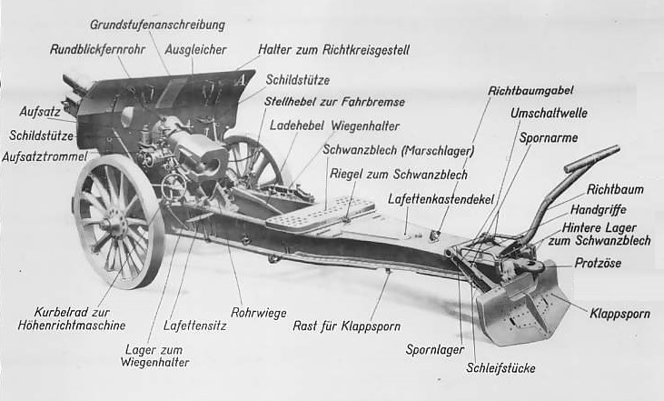
The gun cradle was fitted with rear mounted trunnions that pivoted in bearings at the top front of the saddle. To balance the weight of the gun, two spring equilibrators were fitted on either side at the front of the saddle with the upper ends attached via brackets to the trunnions. The tops of the equilibrators can be seen in the above drawing just behind the splinter shield on either side. Elevating arcs were fitted underneath the cradle on either side which engaged with a transverse pinion shaft that was rotated via a worm gear by the elevation hand wheel to the left of the breech. In order make loading new rounds easier at higher elevation angles, the sFH 13 was fitted with a loading handle (ladehebel). When pushed forward, this disconnected the gun cradle from the elevating arcs and allowed the gun to be lowered . Once loaded, the gun could be pulled back up and locked back in the elevating arc using the loading lever.
The gun was transported in one load by being hitched to a two wheel limber pulled by 6 horses.
Gun Design
The original sFH 13 gun was 2.09 m or 14 calibres long with the rifled part of the barrel being 11 calibres or 1.65 m in length. This was increased to 2.54 m or 17 calibres in the lg. sFH. The gun was of built up construction with the jacket shrunk on to the rifled tube and extending for about half of the length of the barrel. A guide tray was attached to the gun to allow it to slide along runners on either side of the top of the cradle during recoil. The front of the tray was attached via a tube shrunk on to the gun and the rear of the tray was attached to projections underneath the jacket and breech.
The jacket was shaped at the rear to support a horizontal sliding breech block of Krupp design. The breech was opened using a single motion lever on the right of the breech that moved the breech block to the right exposing the breech and ejecting any cartridge in the chamber. The breech incorporated an axial striker to fire a loaded cartridge which was fired using a lanyard fitted to the trigger arm on the right of the breech.

Recoil System
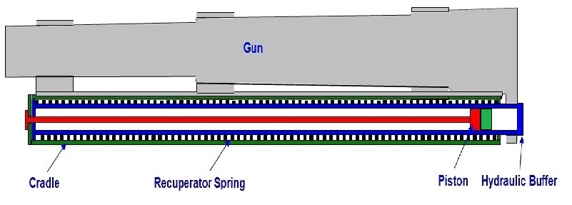
The sFH 13 originally used a hydro-spring recoil system mounted within the cradle. This consisted of a oil filled hydraulic buffer whose cylinder was connected to a lug under the breech with a coaxial spring mounted on the cylinder to form the recuperator. The hydraulic piston was fixed to the end of a rod attached to the front of the cradle.
As the gun recoiled and the hydraulic cylinder was pulled backwards, the oil was forced to flow through the piston resisting its movement and absorbing the energy of recoil. The piston was fitted with ports for this purpose but was also fitted with a rotating valve with a similar set of ports. The rotating valve was keyed into a pair of spiral grooves in the surface of the hydraulic cylinder that caused it to rotate when the gun recoiled. At the start of recoil, both sets of ports were aligned to provide maximum oil flow rate but, as the gun recoiled and the rotating valve rotated, a point was reached where the sets of ports were no longer aligned and the flow of oil was stopped bringing the recoil to an end. At the same time that the hydraulic cylinder recoiled backwards, it compressed the large coaxial spring so that, once the recoil had been brought to an end, the spring forced the gun back into battery.
Even using rear mounted gun trunnions that limited the height movement of the breech, the recoil length had to be shortened as the gun was elevated in order to stop the breech hitting the ground. The sFH 13 used a variable recoil mechanism for which Rheinmetall was given some credit. The length of recoil was varied by rotating the piston rod as a function of the gun’s elevation angle to change the cut off point for oil passing through the piston. In the sFH 13, the front end of the piston rod was fitted with a pinion that engaged with a toothed arm on the end of a control rod mounted inside the cradle. The control rod was rotated by a mechanism near the left gun trunnion as the gun was elevated which in turn rotated teh piston rod and shortened the length of recoil. The recoil length varied between 1.565 m and 1.065 m
However, at the start of WW1 after heavy use, it was found that the recuperator springs would break in a similar way to the problem found with the British Ordnance QF 18-Pdr and a similar solution was found by switching to a hydro-pneumatic recoil system. In the new recoil system, the original hydraulic cylinder and spring were replaced by a long cylinder block with 3 cylinders bored along its length that recoiled with the gun. One of these was used as the hydraulic cylinder with the piston rod connected to the front of the cradle as before. The oil filled recuperator hydraulic cylinder was fitted with a piston on the end of rod also connected to the front of the cradle. As the gun recoiled, the oil in front of the piston was forced into the third high pressure air cylinder compressing the air inside. When the recoil was brought to an end, the compressed air forced the oil back into the hydraulic cylinder which in turn returned the gun to battery. The air cylinder was maintained at a pressure of about 600 psi to keep the gun in battery.
Unlike the British modification of the QF 18-Pdr, the hydro-pneumatic recoil system fitted inside the original cradle and the modified gun was indistinguishable from the original from the outside. Despite the new recoil system being a success, not all of German industry had the capability to manufacture it and therefore the simplified sFH 13/02 was introduced to ease these difficulties as described above which included reverting back to a hydro-spring recoil system. Since the recoil forces were less in the long L17 gun, this was not a problem.
Sights
The sights on the sFH 13 were similar in concept to those on the earlier 10.5 cm lFH 98/09 and were fixed via a bracket to the end of the left-hand trunnion and therefore elevated with the gun. These sights weresaid to be reciprocating in order to overcome the problem caused when the carriage wheels were not level which was the norm. This led to a tilt of the gun trunnions which then caused the vertical plane containing the gun to rotate in azimuth relative to the centre line of the carriage in the direction of the lower wheel made worse by the high angle trajectories used by howitzers. If not corrected, this would lead to a large azimuth sighting error. To overcome this problem, the sights had to be tilted back into the vertical plane using the lower left-hand knob which aligned them with the vertical plane through the gun. A cross-bubble (Radstandlibelle) was provided to facilitate the alignment.
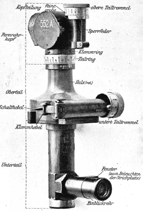
The sights were fitted with a dial sight or panoramic telescope (Rundblickfernrohr) for indirect fire. These were both provided with an adjustment and dial (Teilschreiber) to allow deflection to be added to the sight, in particular, to account for the spin drift of the projectiles. The sighting devices were mounted on top of a toothed sight arc that was raised or lowered using either the course adjustment knob (Schnelltrieb) on the left-hand side of the sight body or by using the fine control knob at the back (Schneckentrieb). Raising the sight arc tipped the sights forward imposing a negative elevation to them.
The sight body was provided with a range drum (Trommel) linked to the sight arc that indicated the range for each of the different charges used with the gun. An adjustable pointer (Zeiger) was used to select the appropriate scale. The sight arc also mounted an adjustable clinometer (Winklemesser) to allow the elevation of the gun to be set. To do this, the angle of sight was first set on the clinometer (angle of the target above the horizontal through the sights) and the range then set on the range drum. By elevating the gun until the clinometer bubble was level then achieved the required quadrant elevation (elevation of gun above the horizontal plane).

Rather than using a conventional telescope as the direct fire aiming device, the lFH 16 used a collimating sight. This type of sight consisted of a rectangular hood through which the target was viewed together with a small collimator in the lower part. The collimator generated a cross-hair reticule in the field of view of the sight effectively focused at infinity. Therefore, what the gun layer saw when looking through the sight hood was the target with the reticule superimposed on it with very little parallax. In use, the gun layer positioned his head about 10 inches behind the sight to use it properly.
Indirect fire was carried out using what the British termed a dial sight and the Germans called a Rundblickfernrohr. The original version of this type of sight was invented in 1906 by a German called Goertz and took the form of a panoramic telescope with an adjustable sighting head that could be rotated from 0 – 360 degrees or 0 – 6400 MILs. The eyepiece was fixed and aligned with the axis of the gun. The sighting head was equipped with an azimuth scale graduated in 100’s of MILs and was normally adjusted using a micrometer knob graduated in 10’s of MILs. The sight was also fitted with another micrometer at the top to allow adjustment of the angle of sight.
During indirect fire, the range, angle of sight and bearing were worked out by a plotting officer using a map showing both the target and gun positions. The target bearing was defined relative to an aiming point defined for the gun which could be a prominent feature in the landscape or could be aiming posts specially set up for this purpose. To aim the gun in the target direction required the relative bearing to be set up on the panoramic dial sight and then the gun traversed until the aiming point was centred in the sight which pointed the gun at the target.
Ammunition
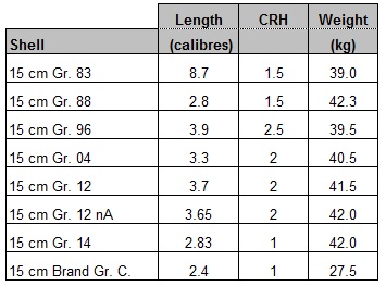
The sFH 13 used separate brass cartridge cases that provided a choice of 7 separate charge for the short version and 8 for the long version sizes depending on the range required. The high explosive shells fired by the sFH 13 evolved over time and both their length and calibre radius head (CRH) changed.
The earlier shells were filled with TNT but when WW1 started, as was the case in the other combatant nations, Amatol started to replace TNT as it was cheaper to manufacture. The Brand Gr. C was an incendiary shell filled with incendiary cylinders that ignited when the shell exploded.
The sFH 13 shells were typically fitted with either the Gr Z 96/04 or G Z 04 percussion fuzes with the latter providing an optional delay allowing the shell to penetrate further before detonating.
The sFH 13 also fired gas shells based on using the Gr. 12 nA shell fitted with the Gr. Z. 04, 9, 17 or 14 nA fuzes. The gas shells were marked with either green crosses, yellow crosses or blue crosses. The green cross shells contained chlorine, phosgene or diphosgene which were designed to cause breathing problems. The blue cross shells contained diphenylchlorarsine (DA) in a bottle that was surrounded by TNT. When the shell exploded, the DA was reduced to a fine powder which caused vomiting when inhaled. The yellow cross shells contained the liquid dichlorodiethyl sulphide which when released to the atmosphere produced a blistering gas which the British called Mustard Gas because of the smell it produced.
15 cm schwere Feldhaubitze 13 Specifications
-
- Length: 5.60 m
- Maximum Width: 1.53 m
- Wheels: Wooden 1.23 m in diameter
- Weight of Gun & Carriage: 2200 kg
- Length of Gun: 2.09 m or 14 calibres for original version
- Length of Gun: 2.54 m or 17 calibres for long or lange version
- Bore: 14.97 cm
- Muzzle Velocity: 365 m/s for sFH 13 and 377 m/s for lg sFH 13
- Maximum Range: 8,500 m for sFH 13 and 8,900 m for lg sFH 13
- Trail: Box trail
- Recoil System: Hydro-pneumatic for sFH 13 and hydro-spring for lg sFH 13/02
- Maximum Recoil: 1.565 – 1.065 m
- Rifling: Polygroove with modified plain section
- Length of Rifling: 11 calibres (1.65 m) for sFH 13
- Twist: Progressive 1 turn in 35.9 to 1 turn in 17.8 calibres
- Grooves: 36
- Firing Method: Percussion
- Elevation: 0° to +45°
- Traverse: -2.5° left to +2.5° right
![]()