

The US army had not developed their own heavy field gun for use during WW1 and therefore adopted both British and French weapons as a result. These included the British 8 inch and 9.2 inch howitzers, the French 155 mm Mle 1917 Schneider and the 155 mm Mle 1917 GPF. The latter was used as a long range heavy field gun with US manufactured versions designated as the 155 mm Gun Materiel M1918. The M1918 remained in US service until the end of WW2.
However, following WW1, the Westervelt Board was convened to review the use of artillery during the war and to make recommendations regarding future artillery requirements. Although the M1918 was considered to be adequate as the main heavy field gun in the interim, it recommended the development of a new carriage for the gun to provide 0° – 65° of elevation and a range in excess of 25,000 yds. This eventually resulted in the 155 mm Gun M1 adopted in 1938 that was nicknamed ‘Long Tom’, a term used in both US and British military circles to describe a very long range gun. The ‘Long Tom’ remained in US service throughout WW2 and the Korean War (1950-53) and was also provided to the British under Lend-Lease in the early years of WW2.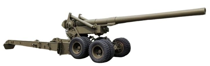
Gun Design
In contrast with the 38 calibre M1918 gun that was of built-up construction, the 155 mm gun M1 was forged from a single piece of steel with a length of 277 inches or 45 calibres that was subjected to autofrettage. This manufacturing process resulted in residual compressive stresses being imparted to the gun barrel in a similar way to that found in built-up or wire wound guns that then resisted the internal pressure of firing. The bore was rifled for most of its length with the chamber for the propellant charge machined into the rear part. Three guide rings were shrunk on to the gun to attach it to the slide or sleigh on which the gun recoiled in guides in the cradle.
The breech ring was screwed on to the end of the gun. Originally, a breech bush was fitted into which the interrupted threads to take the breech screw were cut. However, in the M1A1 version of the gun, the breech bush was omitted. The M2 model of the gun was similar to the M1 and used a breech bush but differed in having an enlarged chamber. The breech ring was fitted with a lug underneath to connect the gun to the recoil system.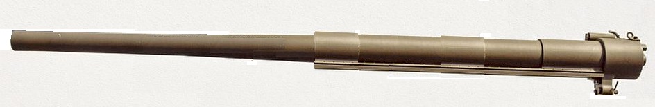
The breech used an Asbury single motion mechanism with a Welin type breech screw with stepped, interrupted threads. The breech was operated by a lever on the right. When pulled backwards, this unlocked the breech screw and then swung it clear to the right to allow the next round to be loaded. The breech was fitted on top with a spring loaded counterbalance device that helped to counter the effect of gravity on opening and closing the breech especially at higher elevation angles.
The breech screw was fitted with a mushroom headed axial vent for use with bagged cartridges that incorporated an obturator pad behind the mushroom head. When the breech was closed, the obturator pad was forced against the coned rear of the breech. When the loaded cartridge was fired, the chamber pressure pushed the axial vent backwards slightly which, in turn, pushed the obturator pad outwards hard against the sides of the chamber fully sealing it. The cartridge was fired via a lanyard using a percussion lock and a percussion tube or primer as the US called them inserted into the back of the axial vent. The cartridges included igniter pads of gunpowder sewn into pockets at the rear that were ignited by the flash from the percussion cartridge traveling down the central hole in the axial vent.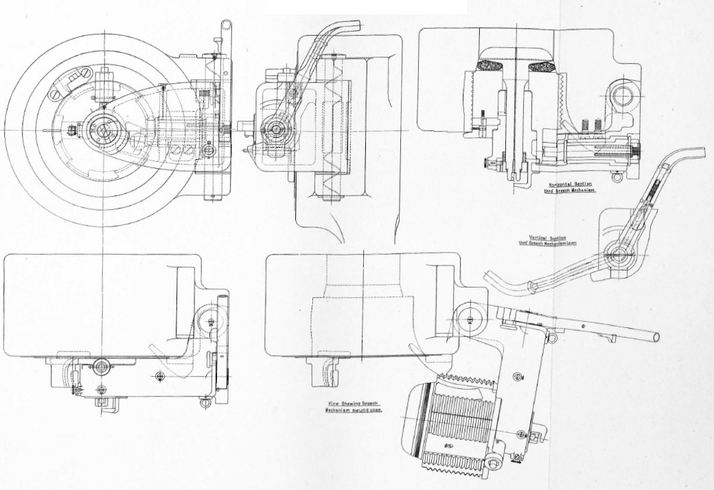
Carriage
The M1 carriage used a split trail with legs that pivoted on the bottom carriage with detachable spades fitted at the rear. The bottom carriage was fitted at the front with two-axle dual tired wheels for transportation but was lowered on to the ground using a hand powered lifting mechanism between the wheels. Before the bottom carriage was lowered, detachable front spades were fitted just behind the rear set of wheels. When travelling, both the front and rear spades were stowed in brackets on the trail legs.
The bogie wheels were fitted with drum brakes that are operated when travelling by an air brake system controlled by the towing vehicle. However, when parked, brake levers on the front of the carriage were used to operate the brakes manually.
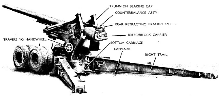
The cradle was U-shaped with trunnions mounted on either side with the elevating arc fitted underneath. The cradle housed the hydro-pneumatic recoil system connected to the lug underneath the breech of the gun with the gun recoiling on its slide along guides on either side of the cradle. The gun and cradle were supported on trunnion bearings on the top carriage above which were the mounting brackets for the two equilibrators used to support the unbalanced weight of the gun and cradle. The top carriage pivoted in azimuth on the bottom carriage as part of the traversing mechanism.
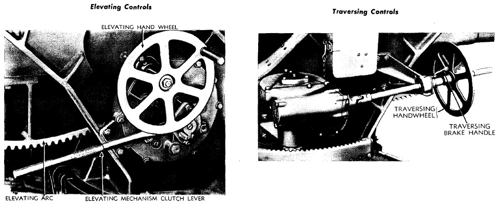
The elevating mechanism was mounted on the right side of the top carriage. The elevating hand wheel rotated a transverse mounted pinion via a set of gears that meshed with the elevating arc under the cradle. The elevating mechanism was fitted with a brake to lock the gun at a particular elevation angle with the brake released by lowering the clutch lever underneath the hand wheel. The mechanism provided 1° 50′ of depression and 63° 20′ of elevation. The traversing mechanism was mounted on the left side of the top carriage. The hand wheel rotated a vertical pinion via a flexible link and a worm and worm wheel with the pinion meshing with the curved rack fixed to the bottom carriage. The traversing hand wheel was also provided with a brake lever just in front of it to lock the mechanism and stop it turning. The traversing mechanism provided 30° of traverse to both the left and right.
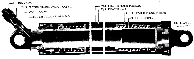
To support the weight of the unbalanced gun and cradle resulting from the rear set trunnions, pneumatic equilibrators were employed on either side. Essentially, these consisted of a cylinder fixed to the top carriage at the rear and contained a piston on the end of a rod attached to the cradle at the front. In front of the piston was nitrogen gas at a nominal pressure of about 1300 psi. When the gun was lowered, this moved the piston forward compressing the nitrogen further and producing an upwards force that compensated for the increasing preponderance weight of the gun and cradle.
Transporting
To transport, the gun was disconnected from the recoil system and winched backwards with the breech then supported on the travelling lock. The bottom carriage was also raised off the ground to be supported on its front bogie wheels. The gun could be trailered directly from the rear of the trail legs but normally a two-wheel limber was used to support the rear of the trail as shown. Originally, it was towed by a Mack NO 7½-ton 6×6 truck but, from 1943, this was generally replaced by the tracked M4 High Speed Tractor.
![]()
Recoil Mechanism
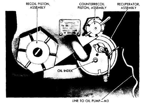
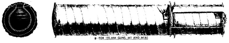
The recoil system consisted of 3 cylinders whose rear configuration is shown below. The lower left cylinder was the hydraulic buffer responsible for absorbing much of the recoil energy. The recuperator or counter-recoil assembly as the US called it was then responsible for storing the remaining recoil energy and for returning the gun to battery. It consisted of a high pressure (HP) cylinder and a liquid cylinder with the HP cylinder shown bottom right and the liquid cylinder shown just above it.
The hydraulic buffer consisted of a cylinder filled with oil fixed to the front of the cradle. The cylinder housed a piston on the end of a rod connected to the lug beneath the breech. Inside the hollow piston rod was a control rod connected to the front of the cradle. During recoil, as the piston was pulled backwards, oil was forced from the rear of the buffer cylinder to the front through small openings in the piston and past grooves in the control rod.
Inside the recuperator liquid cylinder was a piston on the end of a rod also connected to the lug underneath the breech. As the gun recoiled, oil to the rear of the piston was forced through a connection into the rear of the HP cylinder where it pushed a floating piston forwards to compress the nitrogen in the front of the cylinder. When the recoil ended, the high pressure of the nitrogen then forced the floating piston backwards that, in turn, forced the oil back into the liquid cylinder pushing the piston forwards and returning the gun to battery. In order to bring the gun to a gentle stop during run out, a smaller rod on the rear end of the control rod entered an oil filled buffer that slowed down the final stage of movement.
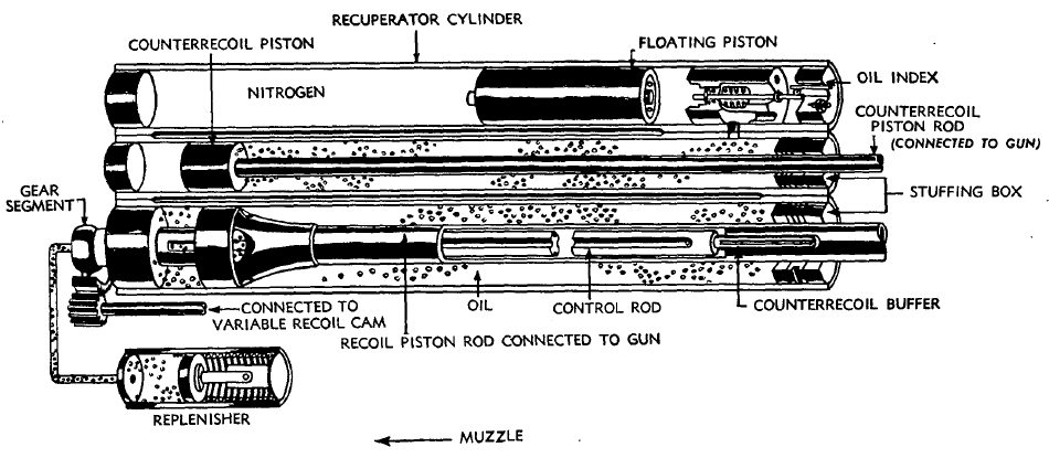
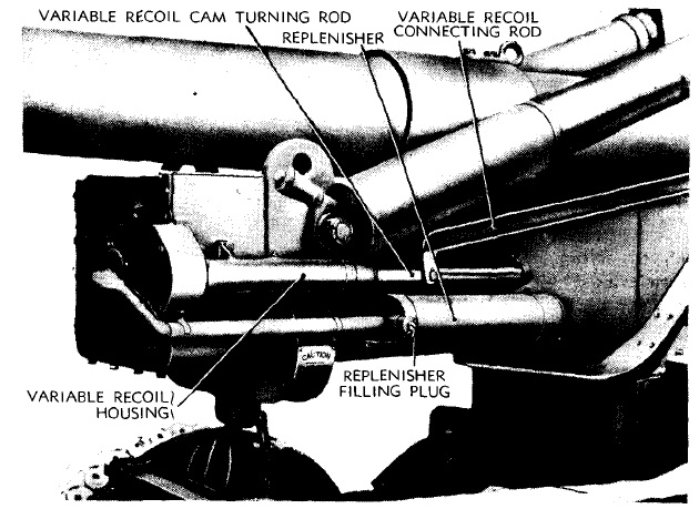
The M1 carriage was fitted with a variable recoil system that changed the length of recoil as a function of the elevation angle of the gun. At about 10° elevation, the length of recoil was about 65 inches maximum but, at about 63°, this reduced to about 34 inches maximum in order to prevent the breech from hitting the ground. The variable recoil length was achieved by rotating the control rod as a function of the elevation angle of the gun which changed the effective width of the grooves in the control rod through which oil had to pass during recoil. The effect of this was to increase the rate at which the recoil energy was absorbed thus shortening the length of recoil as the gun elevated. Rotation of the control rod was achieved via a connecting rod fixed to a pivot on the top carriage just below the left-hand trunnion. As the gun elevated, the connecting rod was pulled backwards along with the cam turning rod that rotated an outer shaft with a pinion on the front end that engaged with the gear segment on the buffer control rod.
Gun Sights
The M1 carriage used two-man laying. This meant that the crew member on the left of the breech layed only for direction using a panoramic telescope with the crew members on the right of the breech using a gunner’s quadrant (clinometer) to lay for elevation. The sights used on the M1 carriage were non-calibrating. This meant that a separate Gun Rule had to be used to work out the quadrant elevation required for a given range and muzzle velocity that was then applied to the sights.
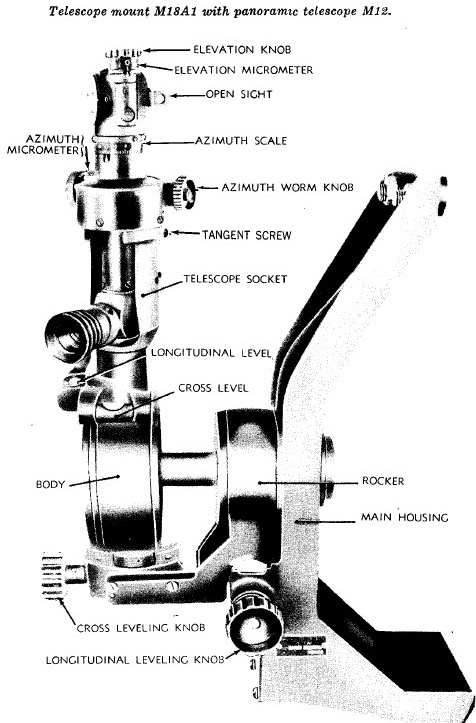
The M12 panoramic telescope fitted into a socket on the M18 telescope mount and was offset by 45°for ease of use. This was a reciprocating sight mount that was able to compensate for the gun trunnions not being level, which was the norm. The result of trunnion tilt was to rotate the vertical plane through the gun barrel in azimuth in the direction of the lowest trunnion. If uncompensated, this would lead to a large sighting error that increased in magnitude as the gun was elevated. The effect was compensated for by tilting the sight bracket body sideways about a pivot that was maintained parallel to the gun. The pivot was inside the sight mount body and rotated with the gun via a shaft connected to the left-hand trunnion. The adjustment was carried out using the cross-levelling knob and the cross-level bubble. The panoramic telescope also needed to be levelled longitudinally using the knob and longitudinal level.
The M12 panoramic telescope provided  4 x magnification and a field of view of 10°. It used a fixed eyepiece at the bottom but with a sighting head at the top that could be rotated through 360° (6400 mils) using the quick release lever or the azimuth micrometer with an azimuth scale provided on the body. The scale was graduated in 100 mil intervals numbered 0 – 32 in both directions. The graduations on the azimuth micrometer were from 0 – 100 miles in 1 mil intervals. The telescope also included a separate micrometer knob to provide a deflection adjustment to account for drift or wind effects. The sighting head itself was provided with an elevation adjustment knob.
In indirect fire mode, the target direction was specified relative to an aiming point that could be a prominent feature in the landscape or aiming posts specifically set up for the purpose. The aiming point could be in front of the gun, to the side or behind it. In practice, the target relative bearing was set up on the panoramic telescope and then the gun traversed until the aiming point was centred in the sight. At that point, the gun was aligned with the target direction.
The quadrant elevation for the gun was set using a gunner’s M1 quadrant mounted on the M1 quadrant mount fixed to the right-hand gun trunnion. In order for the quadrant to give an accurate setting, the mount had to be tilted into the vertical plane using the cross-level and adjusting knob. The quadrant elevation was set on the quadrant using the coarse scale graduated from 0 – 800 mils (0° – 45°) when used one way up or 800 – 1600 mils (45° – 90°) when used the other way up with both scales graduated in steps of 10 mils. The micrometer was used for fine adjustments and graduated from 0 – 10 mils. Once set, the gun was elevated until the bubble was centred.

Gun Crew
The 155 mm Gun M1 required a crew of up to 14 to operate the weapon with the main functions being:
No. 1: The senior officer commanding the gun.
No. 2: Operated the breech mechanism and fired the gun.
No. 3 : Operated the panoramic telescope mount and traversed the gun.
No. 4: Operated the gunner’s quadrant and elevated the gun.
No. 5: Operated the gunner’s quadrant and elevated the gun.
No. 6: Responsible for preparing and loading cartridges.
No. 7: Prepared the shells and carried them on the loading tray to the gun.
No. 8: Prepared the shells and carried them on the loading tray to the gun.
No. 9: Prepared the shells, carried them on the loading tray to the gun, rammed and sponged.
No. 10: Prepared the shells, carried them on the loading tray to the gun and rammed.
No. 11: Prepared the shells and rammed.
No. 12: Prepared the shells and rammed.
The remaining crew members would have been used as reserves to replace any casualties.
Ammunition
The GPF guns used bagged cartridges that could be made up from a base section 6.5″ in diameter and 25.25″ long to produce the normal charge of 18 lb of smokeless powder, or with an increment section 11.75″ long could be added to produce a supercharge of 26 lb of smokeless powder for use at extreme ranges. An igniter consisting of 8 oz of black powder was sewn into the base charge that was ignited by a percussion primer inserted into the back of the breech.
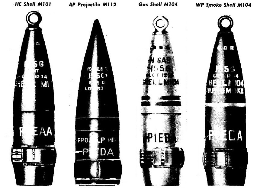
Five different types of shell were fired by the 155 mm Gun M1: high explosive (HE), armour piecing (AP), gas and smoke. These were used with super-quick and delay fuzes M51, M54 or M55 together with the mechanical time M67 fuze providing a time delay of up to 75 seconds for air bursts.
The M101 HE shell weighed 95 lb, was 26.79″ long and was filled with a bursting charge of up to 16 lb of TNT or Amatol. The M112 AP shell weighed 108 lb, was 23.62″ long and contained a bursting charge of 1.44 lb of Explosive D. It was fitted with a windshield to provide armour penetration. The M104 gas shell was of similar size and weight to the HE shell and contained a chemical filling of 11.7 lb together with a small bursting charge. The M104 smoke shell weighed 99 lb, was 26.82″ long and contained a white phosphorous filling of 16.9 lb together with a small bursting charge. All the shells except for the AP had a 11 calibre radius head and were boat tailed.
155 mm Gun M1 Specifications
-
- Length when Travelling: 36 ft 10 inches
- Maximum Width: 99 in
- Wheels: 20 inch wheels with 11 inch pneumatic tyres
- Weight of Gun & Carriage: 27,700 lb (in firing position)
- Length of Gun Barrel: 277.37 inch (45 cal)
- Bore: 155 mm
- Weight of Gun & Breech: 9,595
- Muzzle Velocity: 2,800 fps (HE shell)
- Maximum Range: 25,715 yds (HE shell)
- Trail: Split trail
- Recoil System: Hydro-pneumatic
- Maximum Recoil: 65 inches at 10° elevation and 35 inches at 63°
- Rifling: Polygroove with plain section
- Twist: Right-hand 1 turn in 20 calibres
- Grooves: 40
- Firing Method: Percussion
- Elevation: -1° 50′ to +63° 20′
- Traverse: -30° left to +30° right
![]()