

In 1867, Germany found that the largest siege gun available at the time, a 24-pdr, was not able to destroy certain types of modern fortifications. This led to trials of a 21-cm mortar designed by Major Wegener of the APK (Artillerie-Prüfungs-Kommission or Artillery Testing Commission). The trials were successful and, as a result, 12 of these mortars with bronze tubes were built and later used in the siege of Strasbourg during the Franco-Prussian War (1870-71). These mortars were followed by more modern steel versions in the form of the 21 cm Mörser models 1880 and 1899 both designed and built by Krupp.
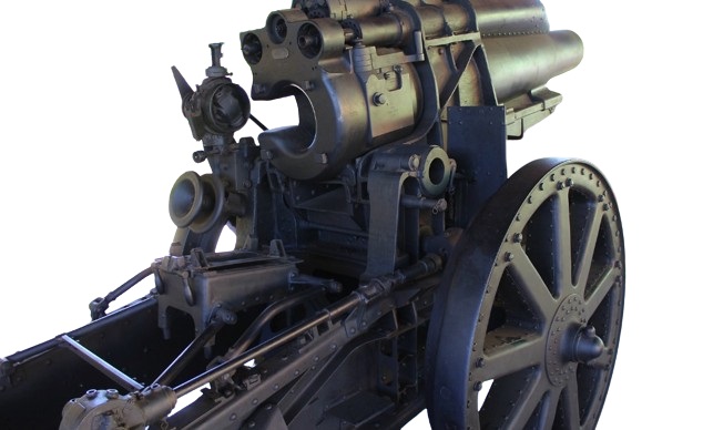
However, the 1899 model did not incorporate a recoil system and was soon rendered obsolete by developments elsewhere. As with other German artillery guns of the late 19th Century, the APK asked Krupp and Rheinmetall to develop a more modern version of the 21 cm mortar. Krupp produced 3 versions of the so-called 21 cm Versuchsmörser (experimental mortar) with the first 2 being rejected but the 3rd version was considered more promising and 8 of these were ordered in 1906, some of which were used in WW1. This was in contrast with the Rheinmetall 21 cm Versuchsmörser designs that were not adopted. The Krupp 21 cm Versuchsmörser 06 shown below used a hydro-spring recoil system in a box-like cradle beneath the gun with rear mounted trunnions, the latter necessitating the use of a pair of spring struts (equilibrators) to support the unbalanced weight. 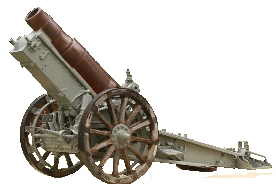
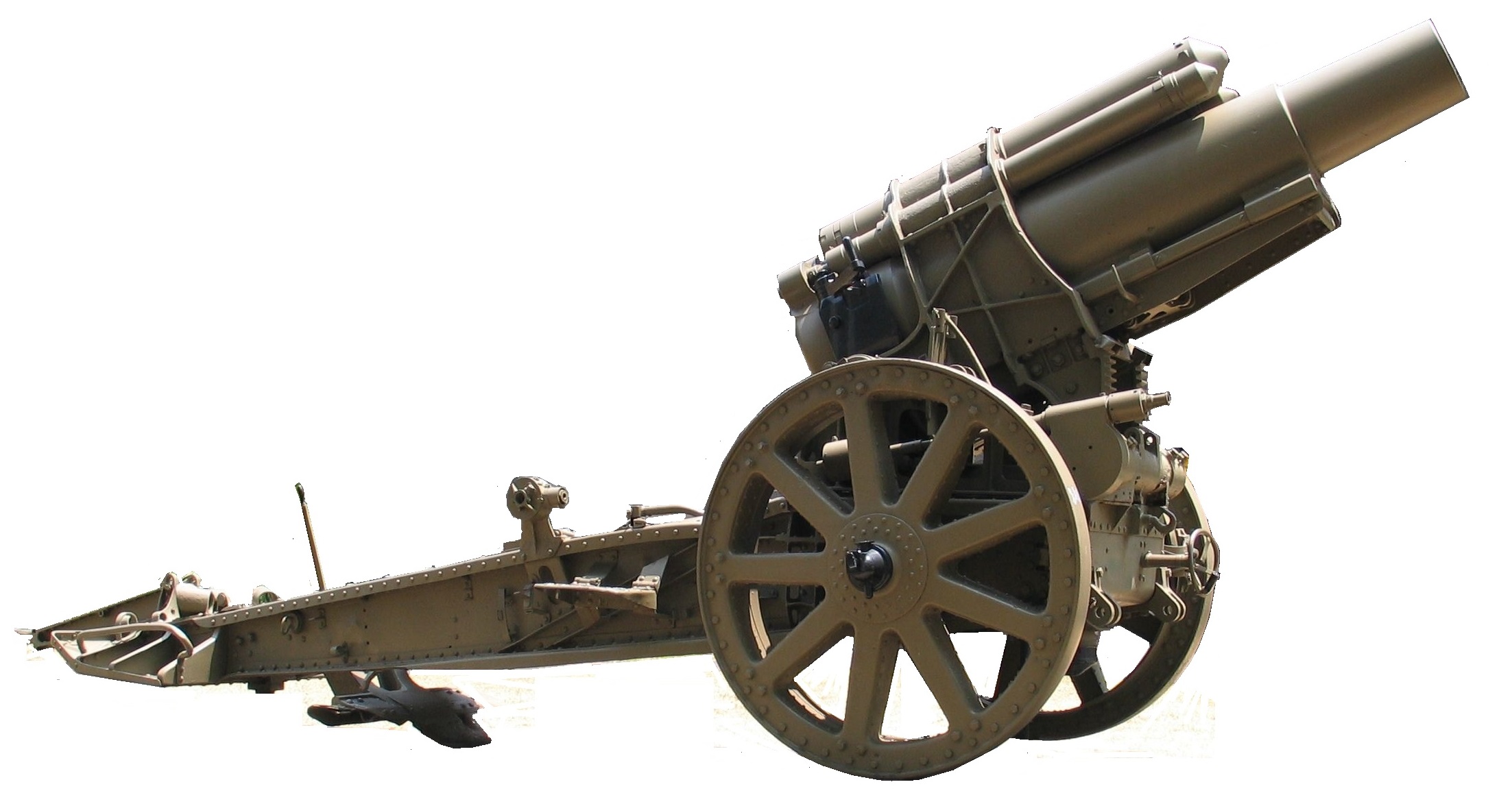
However, the main limitation of the 21 cm Versuchsmörser 06 was its range of only 7 km with its 10 calibre long gun and it was decided that a 12 calibre gun was needed to give the required range of closer to 9-10 km. The design was therefore modified to eventually produce the 21 cm Mörser 10 adopted in 1910. Apart from using a lengthened gun, the major change was to a hydro-pneumatic recoil system that was mounted above the gun rather than below it. In this form, the 21 cm Mörser 10 served throughout WW1 although, in the same way as other WW1 German artillery pieces, a longer barrelled version, the 21 cm Mörser 16, was adopted in 1915 to give a slightly greater maximum range.
Gun Design
The gun was 2.57 m or 12 calibres long with the rifled part of the barrel being 8 calibres or 1.67 m in length. The gun was of built up construction with the jacket shrunk on to the rifled tube and extending for about three quarters of the length of the gun. Three guide brackets were cast on the jacket to support the gun on the recoil bed and lugs were cast above the breech to connect it to the recoil system.
The jacket was shaped at the rear to support a horizontal sliding breech block of Krupp design. The breech was opened using a single motion lever on the right of the breech that moved the breech block to the right exposing the breech and ejecting any cartridge in the chamber. The breech incorporated an axial striker to fire a loaded metallic cartridge that was operated using a lanyard fitted to the trigger arm on the side of the breech block. 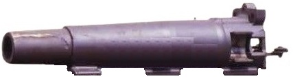
Carriage Design
The 21 cm Mörser 10 was mounted on a box trail with a gap between the side arms in the front half to provide space for the gun to recoil. The trail was mounted on metal box section spoked wheels to which a radgürtel, or girdle as the British called them, could be attached providing 10 pivoted shoes on each wheel. These shoes provided a much greater bearing surface for use on soft surfaces. The wheels were fitted with inner, smaller diameter rims against which brake shoes acted at the front operated by a hand wheel on the front of the carriage. As was normal German practice, the rear of the trail mounted a deployable spade (klappsporn) and a horizontal tail plate (schwanzblech) to stop it sinking into the ground. The rear of the trail also mounted a deployable metal traversing pole (richtbaum).
The gun was mounted in a cradle consisting of a bed fitted with guide rails either side on which the gun recoiled with trunnions fitted at the rear. A hollow steel casting was attached to the recoil bed surrounding the centre of the gun to which the recoil system was attached above the gun. Two elevating arcs were fitted at the front of the cradle casting that allowed the gun and cradle to be elevated.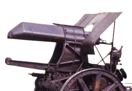
The gun cradle was supported by a low profile saddle on which the gun elevated on its rear mounted trunnions. The elevating arcs engaged with pinions on a shaft that ran across the front of the saddle rotated via a worm drive and articulated shaft back to a hand lever on the right-hand side of the carriage. This lever was used to quickly lower the gun to the loading position and to return it back to its original elevation once a round had been loaded. The gun layer on the left of the carriage was provided with two coaxial hand wheels. The inner one was connected to a gearbox on the elevating mechanism operating shaft via a cross shaft and enabled the gun layer to make fine adjustment to the gun’s elevation when using the sights.
The saddle rotated in the horizontal plane on a pivot in the centre of the saddle on top of the trail to provide up to 2° of traverse to the left or right. The saddle was traversed by a rack and pinion operated by the gun layer using the outer hand wheel on the left of the trail. In order to support the weight of the gun and cradle on its rear mounted trunnions, the 21 cm Mörser 10 was fitted with a single large spring strut. This attached to the cradle just behind the elevating arcs and then passed through the traversing pivot in the saddle with its lower end pivoted under the front of the trail.
 The trail was fitted with steel steps on either side on which the gun crew could stand to access the breech and the sights. The trail was also fitted with a shell lift that could be lowered to allow a shell to be placed on the tray before being swung upwards to allow the shell to be rammed into the breech.
Transportation
Since the maximum load that could be pulled by 6 draught horses was about 4,000 kg at most, the 21 cm Mörser 10 had to be broken down into two separate loads for horse transport as shown below. This was achieved by sliding the gun off the recoil bed and onto the bed of its 4 wheel transport wagon leaving the trail and cradle to be transported as a separate load after being hooked up to a small 2 wheeled limber.
![]()
![]()
Recoil System
The 21 cm Mörser 10 was designed with rear mounted trunnions so that the height of the breech changed very little as the gun was elevated. This allowed the gun to recoil up to 1.5 m at all elevation angles and avoided the complication of a variable recoil mechanism to stop the breech hitting the ground at the highest elevation.
Most WW1 German artillery systems used simpler hydro-spring recoil systems but the 21 cm Mörser 10 used a hydro-pneumatic system possibly because this was more compact and allowed it to be mounted above the gun. The recoil system consisted of a central recuperator flanked by two identical hydraulic buffers on either side. Although shown exposed in the picture below, the cylinders were normally covered by an armoured shield over the parts of the cylinders in front of the cradle to protect them from battle damage.
Each hydraulic buffer consisted of a cylinder filled with oil that was attached to the gun cradle. Each buffer contained a piston on the end of a rod that was bolted to a lug on the top of the breech. As the gun recoiled, each piston rod was pulled backwards forcing oil to flow past the piston from the rear of the cylinder to the front. The inner surface of the cylinder was grooved to allow the mineral oil to move forwards past the piston in a constricted manner creating the damping force required to help absorb the recoil of the gun.
The recuperator contained a hydraulic cylinder at the bottom and a air cylinder above it. The hydraulic cylinder contained a piston on the end of a rod bolted to a lug above the breech with oil filling the space to the rear of the piston. As the gun recoiled, the oil was forced into the air cylinder where it compressed the air helping to absorb some of the recoil energy of the gun. Although some hydro-pneumatic recoil systems used a floating piston between the oil and the air, it is believed the one on the 21 cm Mörser 10 did not. Once the recoil had ended, the high pressure in the air cylinder forced the oil back into the hydraulic cylinder pushing the piston forward running out the gun at the same time. With the gun run out, the ambient pressure in the air cylinder had to be maintained at at least 600 psi to hold the gun in place. Either by design of the grooves or by the use of a control on the front of the hydraulic buffer piston rod, the final motion of the gun was brought to a gentle end.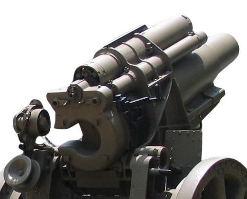
Sights
The 21 cm Mörser 10 was sighted using a rundblickfernrohr 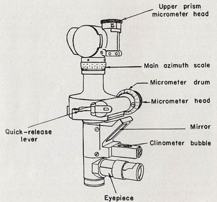 (panoramic telescope) similar to the one shown on the right. This type of sight used a fixed eyepiece for the gun layer but the sighting head at the top could be rotated through 360° using either the quick release lever or via the micrometer knob. The angle of sight could be adjusted using the upper micrometer knob. The rundblickfernrohr used on the 21 cm Mörser 10 incorporated both a longitudinal level and a transverse level, both viewed through the 45° mirror. In practice, in indirect fire, the bearing of the target was set on the sight using an offset angle from an aiming point that was then centred in the rundblickfernrohr. Its mounting bracket was provided with a deflection adjustment via a micrometer knob to allow the sights to be used to compensate for the effects of wind and drift.
The sights were mounted on a transverse shaft that rotated in a bearing in a mounting bracket fixed to the left-hand side of the saddle. This shaft was displaced from the left-hand trunnion to the rear of the breech to put the sights in a convenient place for the gun layer. A control rod connected between arms on the trunnion and the sight shaft transferred the rotational movement from the trunnion to the sights.
The sights were reciprocating to allow for the effects of the wheels, and therefore the trunnions, not being level, which was the norm. This type of tilting caused the plane in which the gun elevated being rotated in azimuth in the direction of the lowest wheel away from the centreline of the carriage and, if uncompensated, resulted in a large sighting error being generated especially at higher angles of elevation. To correct for this effect, the sight bracket had to be tilted sideways back into the vertical plane about a pivot axis that was maintained parallel to the gun. This was achieved via a reciprocating bracket that pivoted on the inner end of the sight shaft that supported the sight bracket on which the rundblickfernrohr and the range drum were mounted. The reciprocating bracket tilt axis was maintained parallel to the gun by the rotation of the sight shaft as the gun elevated. The required tilting of the sight bracket was carried out using adjustment knobs on the reciprocating bracket that tilted it about the pivot axis. The cross level on the rundblickfernrohr was used to adjust the sight bracket into the vertical plane.
On most artillery guns, the sights elevated with the gun but, on the 21 cm Mörser 10, this was not the case. It’s possible that this was done because the mortar was not fitted with a mechanism to allow the gun to be lowered quickly for loading independently of the sights as was the case, for example, on the equivalent British BL 8-Inch Howitzer. On the 21 cm Mörser 10, the sight bracket and the rundblickfernrohr were fixed in the longitudinal place. To use, the rundblickfernrohr needed to be adjusted to be vertical in this plane using its longitudinal level and the adjustment knob and screw underneath the sight bracket connecting it to the mounting bracket on the saddle.
The required target range was set on the sight using the range drum on the right-hand side of the sight bracket that was graduated in range units for each of the charge levels (1-9) with a reader bar provided on top of the drum. The range setting was adjusted using the small hand wheel on the back of the sights. Two indicator arms where provided on the outer end of the sight shaft; the inner one indicated the elevation of the gun and the outer one indicated the range setting on the range drum. After the range had been set, the gun was elevated until the two indicator arms were aligned. They were probably provided in this form to allow the crew member on the right of the trail who lowered the gun for loading to easily see when the gun had been elevated again to roughly the same setting afterwards. The gun layer would then have made any fine adjustment.
Ammunition
The 21 cm Mörser 10 used separate ammunition with the propellant charge contained in a brass cartridge. Nine charge levels were available with different muzzle velocities (MV) matched to the range of the target. For the long 1896 n/A HE shell:
- Charge 1: 2.9 kg of propellant, a MV of 225 m/s and a maximum range of 3.8 km
- Charge 2: 2.6 kg of propellant, a MV of 207 m/s and a maximum range of 3.5 km
- Charge 3: 3.2 kg of propellant, a MV of 241 m/s and a maximum range of 5.0 km
- Charge 4: 3.5 kg of propellant, a MV of 258 m/s and a maximum range of 5.7 km
- Charge 5: 3.9 kg of propellant , a MV of 280 m/s and a maximum range of 6.6 km
- Charge 6: 4.3 kg of propellant, a MV of 302 m/s and a maximum range of 7.4 km
- Charge 7: 4.9 kg of propellant, a MV of 332 m/s and a maximum range of 8.4 km
- Charge 8: 5.2 kg of propellant, a MV of 347 m/s and a maximum range of 8.9 km
- Charge 9: 5.6 kg of propellant, a MV of 367 m/s and a maximum range of 9.4 km.
With the short 1914 shell, the muzzle velocities were higher with, for example, Charge 9 producing a MV of 406 m/s but, surprisingly, a shorter maximum range of 9.1 km.
The 21 cm Mörser 10 fired 3 types of shell: a long high explosive (HE) shell, a short HE shell and a gas shell.
The long 1896 n/a pattern shell weighed 120 kg, had a 2 calibre radius head (CRH) and used a kz. Bd. Z. 10 base percussion fuze. It was filled with a bursting charge of 17.47 kg of TNT originally but later Amatol. The shell was designed to penetrate moderate overhead cover using high angle fire but not thick concrete. The fuze provided a delayed action function when required to detonate the shell after it had penetrated the target.
The short 1914 pattern shell weighed 83.7 kg, had a 1.5 CRH and used a Gr. Z. 04 percussion fuze. It was filled with a bursting charge of 7.7 kg. The fuze provided a non delay action for use against troops or light cover and a delay action using high angle fire against stout overhead cover.
The long Gr. 96 n/A shell was used to deliver 8 L of Green Cross 2 (phosgene) and Yellow Cross (mustard) poison gas weighing 116.5 kg. It was fitted with a Gr.Z. 92 percussion fuze in the nose and contained a bursting charge of 0.878 kg of TNT contained in the central iron tube

21 cm Mörser 10 Specifications
-
- Length: 6.7 m
- Maximum Width: 2.1 m
- Wheels: Metal 1.5 m in diameter
- Weight of Gun & Carriage: 7,029 kg
- Length of Gun: 2.57 m or 12 calibres
- Bore: 21.1 cm
- Muzzle Velocity: 367 m/s (1896 n/A Long Shell Charge 9)
- Maximum Range: 9,400 m (1896 n/A Long Shell Charge 9)
- Trail: Box trail
- Recoil System: Hydro-pneumatic
- Maximum Recoil: 1.5 m
- Rifling: Polygroove
- Grooves: 64
- Firing Method: Percussion
- Elevation: -6° to +70°
- Traverse: -2° left to +2° right
![]()