

In the 1890’s, the 5-Inch BL Howitzer was introduced into British service to provide the artillery with a field gun capable of firing high explosive shells. At that time, the main field gun, the 15-Pdr BL Gun, only fired shrapnel shells. However, during the 2nd Boer War (1899-1902), the howitzer performed badly being too heavy for proper field artillery use and having inadequate range.
In 1901, the Special Committee on Horse and Field Artillery Equipment was established with Cabinet approval chaired by Major-General George Marshall who was a former artillery commander in South Africa. He brought together other artillery commanders with war experience to establish the requirements for a quick-firing howitzer. Designs were invited but none were considered satisfactory and further work needed to be carried out. However, by 1905, prototypes were ordered from the Royal factories and from private industry including Armstrong, Vickers and the Coventry Works which was formed by a consortium of British shipbuilding firms. Testing in 1906 showed that the Coventry Works design was the best and a number were ordered for trials. These trials were successful and resulted in this design being adopted in 1908 as the 4.5-Inch QF Howitzer.
The 4.5-inch howitzer served throughout WW1 and was still in service in the early part of WW2 but with the carriage wheels changed to wheels with pneumatic tyres for mechanised towing. It was eventually replaced by the QF 25-Pdt Gun Howitzer.
Main Design Features
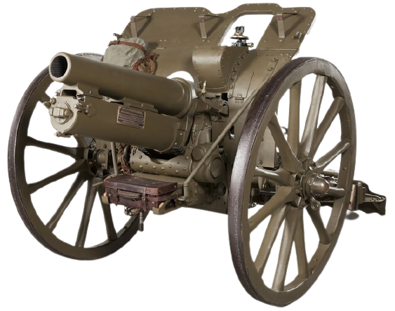
The Mk I carriage employed a box trail with a space for the gun to recoil into between the two side arms. It was fitted with a spade and traversing lever on the back. Axles for each wooden wheel were bolted to the side of the trail and brake shoes were mounted behind the wheels to steady the gun during recoil.
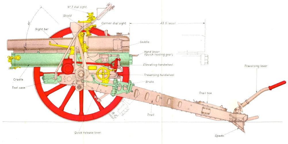
The gun was mounted on a cradle that contained the recoil mechanism. The cradle was supported by its trunnions on a saddle that pivoted on the front of the trail to provide up to 3 degrees of traverse to either side using a traversing hand wheel on the left-hand side of the saddle. The gun was elevated using toothed elevating arcs that pivoted on the trunnions but connected to the cradle at the rear. These were driven by pinions on a shaft through the front of the trail that was connected via a pinion and worm gear to the elevating hand wheel 0n the left-hand side of the gun saddle. However, to facilitate loading of the gun, it was fitted with a quick-loading gear mounted on the cradle and operated by a lever on the right-hand side. When the lever was raised, it freed the cradle and gun from the elevating arcs allowing it to be lowered to the horizontal for easy loading. Pulling the lever down then allowed the gun to be raised again to be re-engaged with the elevating arcs.

The carriage was fitted with a curved bullet-proof shield that was attached to the axle tree and was supported by stays either side in front of the shield. The top of the shield was hinged and could be folded down for travelling. On the left-hand side, the shield was fitted with a hood to protect the dial sight. It was also fitted with a hinged shutter to the left of this to provide a field of view for the bar sight.
A number of leather cases were fitted to the gun for storing equipment. In particular, a tool case was mounted on front of the trail and the dial sight was stored in a case on the right-hand side behind the shield.
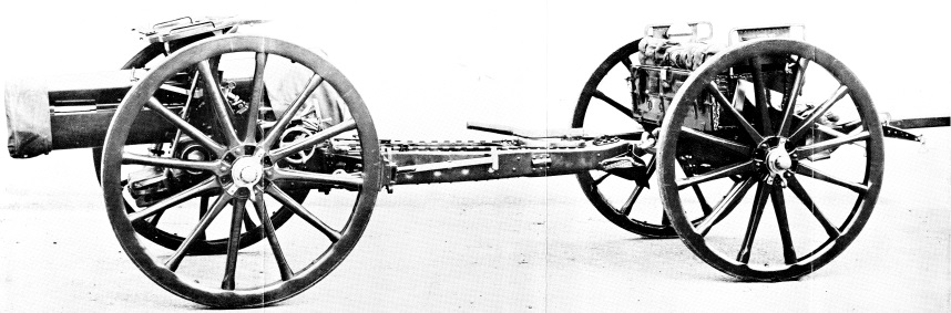
The gun was towed behind a limber pulled by a team of 6 horses. The limber was normally fitted with 6 metal trays, each one carrying a pair of complete artillery rounds (cartridge plus shell). This left room for two further trays of tools although these could also be used for extra rounds.
In the 1920’s the wooden wheels were initially replaced with wheels mounting solid rubber tyres (Mk IR carriage) but in the 1930’s they were replaced with wheels mounting pneumatic tyres (Mk IP carriage) suitable for mechanised towing.
The Mk I & Mk II Gun
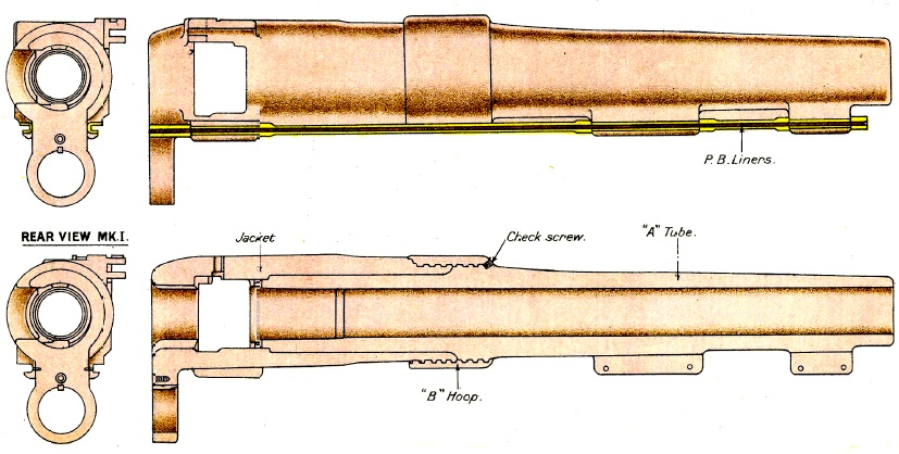
The 4.5-Inch QF Howitzer gun was made from nickel-steel and consisted of three main forgings. The A-tube contained the rifled bore and the cartridge chamber. The jacket was shrunk on to the A-tube followed by the B-hoop that screwed over both. At the rear, the jacket was machined to take the breech block and also incorporated a lug for attachment of the hydraulic buffer cylinder.
The Mk I gun used rifling that increased in twist rate from 1 turn in 41.314 calibre at the breech to 1 turn in 14.78 calibres to within 5.87 inches of the muzzle with the remainder uniform at 1 turn in 14.78 calibres. In comparison, the Mk II gun had a uniform rifling with 1 turn in 20 calibres.
The breech mechanism was of the single motion type with a sliding horizontal breech block actuated by a lever on the right-hand side. The weapon was fired by pulling back the firing lever on the top of the breech block which cocked the mechanism before releasing the striker to hit the firing pin to set off the round. The Mk II had a slightly modified breech to overcome problems with the Mk I.

Recoil Mechanism
The bottom of the gun was fitted with grooved lugs that slid along rails on either side at the top of the gun cradle. The recoil mechanism was housed inside the cradle and consisted of a hydraulic buffer and a spring recuperator. During recoil, the buffer cylinder recoiled with the gun but the buffer piston was fixed in position at the end of the piston rod attached to the front of the gun cradle. During recoil, the oil in front of the piston was forced to the rear through small holes in the piston and, in so doing, absorbed the energy of the recoil and eventually brought this to an end. When the hydraulic cylinder recoiled, it also compressed the recuperator spring that eventually returned the gun to battery after the recoil had stopped.

The piston included a recoil valve, a rotating valve and a retarding valve. The rotating valve engaged with 4 spiral grooves in the surface of the buffer cylinder that caused it to rotate as the cylinder recoiled. The recoil valve was fixed to the piston rod. The rotating valve incorporated 4 butterfly ports that, in combination with the corresponding 4 ports in the recoil valve, determined the size of hole in the piston for the oil to flow through during recoil. At the start of recoil, both sets of ports were aligned but, after a set distance, rotation of the rotating valve closed off the ports thus bringing the recoil to an end.
The gun was fitted with a cut-off gear whose purpose was to shorten the length of the recoil as the gun’s elevation angle was increased – basically, to stop the gun’s breech from hitting the ground. This gear was connected via a rod to the front of the gun cradle and rotated a toothed collar on the end of the piston rod – the amount of rotation was a function of the elevation of the gun. This rotated the rod and recoil valve and, in combination with the rotating valve, determined at what point the valve closed and the recoil was brought to an end. With the gun horizontal, the recoil was limited to 43.5 inches but, with the gun at at 45 degrees, the recoil was reduced to 15.2 inches. The piston also incorporated a retarding valve that functioned in the opposite way to the recoil valve and therefore controlled the flow of oil during run-out of the gun.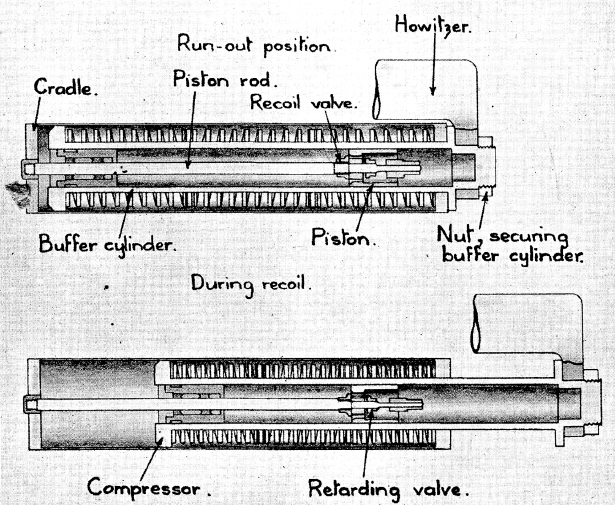
Gun Sights
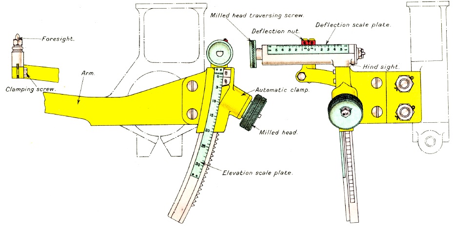
The 4.5-Inch QF Howitzer was fitted with a simple bar sight for direct fire mode that was fixed to the sight mounting bracket attached to the left-hand elevating arc just above the gun trunnion. The front sight was fixed on the bar. The rear sight was adjustable for elevation angle and deflection both adjusted via knurled knobs.
 The sights used for indirect fire on the howitzer were reciprocating which means that they were able to compensate for the carriage wheels not being level, which was the normal state of affairs. When the wheels are not level, the vertical plane in which the projectiles travel is rotated in azimuth in the direction of the lowest wheel.
To overcome this problem, the sight assembly consisted of four separate brackets. The sight supporting bracket was clamped to the left-hand elevating arc and therefore rotated with the elevation of the gun. The sight assembly shown below was fixed to the supporting bracket and could be quickly detached using the clamping handle shown.
The sight assembly was fixed to the supporting bracket via the elevating arc bracket (note: the elevating arc bracket and reciprocating bracket need to be swapped in the drawing below). The oscillating bracket then pivoted on the elevating arc bracket by means of the pivot shown horizontal below. The cross-levelling gear and adjustment knob then allowed the oscillating bracket to be aligned with the vertical plane using the cross-level bubble provided. Since the oscillating pivot was aligned parallel to the gun axis, this meant that cross-levelling the oscillating bracket put it in the same plane as the trajectory of the projectiles and therefore compensated for any tilting of the carriage wheel axle.
The forth bracket was the elevating bracket that pivoted on the oscillating bracket and allowed the elevation of the sight to be varied. This was rotated using a toothed quadrant and a worm gear connected to the hand wheel shown with an elevation scale in degrees provided at the rear of the sight assembly.

The 4.5-Inch Howitzer was primarily designed for indirect fire when the target could not be seen. In indirect fire, the bearing and elevation angle for each gun is calculated by the gun plotting officer and therefore each gun has to be set to the bearing and elevation angles demanded. To set the elevation, a sight clinometer was mounted on the left-hand side of the sight assembly. To set the required elevation, the elevation hand wheel was rotated to dial in the required value on the elevation scale. The gun was then elevated until the clinometer bubble was level.
The target bearing was set using the No. 7 dial sight . The target bearing was specified as the difference in bearing between the target and an aiming point that could be seen with the dial sight and could be in front of or behind the gun. The aiming point was ideally a prominent feature in the landscape (eg church spire) but could be set up via manually deployed aiming posts. To align the gun on the target required the offset bearing to be set up on the sight – this rotated the sighting head at the top by the required angle. The gun laying (No. 3) then traversed the gun until the aiming point was centred in the dial sight at which point the gun was aligned with the target bearing.
The other parameter that had to be taken into account was the spin drift of the projectiles that resulting in them drifting to the right at longer ranges – the azimuth drift angle was a little over 3 degrees producing a drift of many hundreds of yards at the maximum range. This effect was much more pronounced in an howitzer because it used plunging fire that increased the drift rate. This effect was corrected by applying a similar tilt to the dial sight mount.
Ammunition
The ammunition used for the 4.5-Inch QF Howitzer consisted of shells and cartridge cases that were loaded separately into the gun. The cartridge could be loaded with different proportions of propellant to vary the muzzle velocity (MV) of the gun giving the choice of 5 charges. The Mk I cartridge case is shown below that was superseded later in WW1 by the Mk II case that was longer.


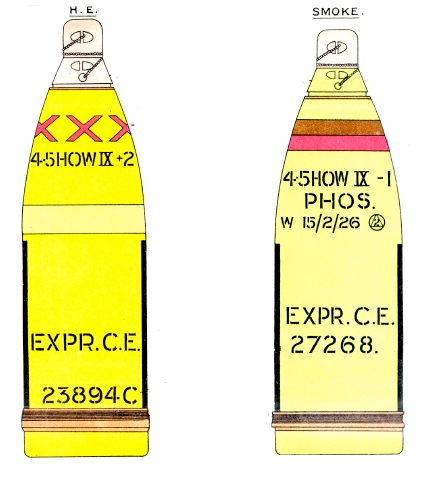
The high explosive (HE) shells were filled with either Lyddite, Trotyl or Amatol with the nominal weight of the shell being 35 lb. When filled with the explosive, a small cavity was left behind the fuze that was filled with an exploder, either Trotyl or C.E., that was used to detonate the main explosive. The fuzes used with the HE shell were either the No. 101 with gaine or the No. 106. The former was the standard percussion fuze but sometimes failed to detonate in muddy ground. The No. 106 was a much more sensitive direct action percussion fuze and was intended to detonate both in soft ground or after hitting barbed wire.
The shrapnel shells were filled with about 490 lead/antimony balls and fitted with a 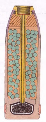 No. 82 time & percussion fuze. The fuze could be set to provide a time delay of up to 22 time units by rotating a time ring. When fired, the time pellet in the nose of the fuze was driven against a needle setting it off that, in turn, ignited a gunpowder trail whose length was determined by the time delay setting. When this burned through, it ignited the powder in the base of the fuze that then ignited the powder in a central tube connecting it to a bursting charge in the base of the shell. When this ignited, it blew off the fuze and propelled the shrapnel balls at high speed out of the front of the shell spraying the ground ahead of the shell. The fuze was also fitted with a percussion pellet that detonated the shell if it hit the ground before the time fuze burned through.
The smoke shell was filled with phosphorus and contains a bursting charge that was detonated on impact using a N0. 106 fuze. This released the burning phosphorus creating clouds of thick smoke.
The star shell was used to illuminate parts of the battlefield. It was fitted with a time fuze and contained a bursting charge, a star composition and a parachute. When the small bursting charge was set off by the time fuze, it ignited the star composition and at the same time created enough internal pressure to shear the pins holding the base of the shell forcing out the contents. The burning star composition then descended slowly on the end of the parachute.
4.5-Inch QF Howitzer Specifications
- Length: 12 ft 3 in
- Maximum Width: 6 ft 3.5 in
- Wheels: 4 ft 8 in
- Weight of Gun & Carriage: 26 cwt 86 lb
- Length of Gun Barrel: 5 ft 10 in
- Length of Bore: 5 ft 1 in
- Bore: 4.5 in
- Weight of Gun & Breech: 9 cwt 13 lb
- Muzzle Velocity: 496-1012 fps
- Maximum Range: 6,800 yd (40 deg elevation and maximum charge)
- Trail: Box
- Recoil System: hydro-spring
- Maximum Recoil: 43.5 in
- Rifling: Polygroove with modified plain section
- Length of Rifling: 4 ft 2 in
- Twist: Mk I: Non-uniform
- Twist: Mk II: Uniform 1 turn in 20 calibres
- Grooves: 32
- Firing Method: Percussion
- Elevation: -5° to +45°
- Traverse: 3° left to 3° right
![]()