

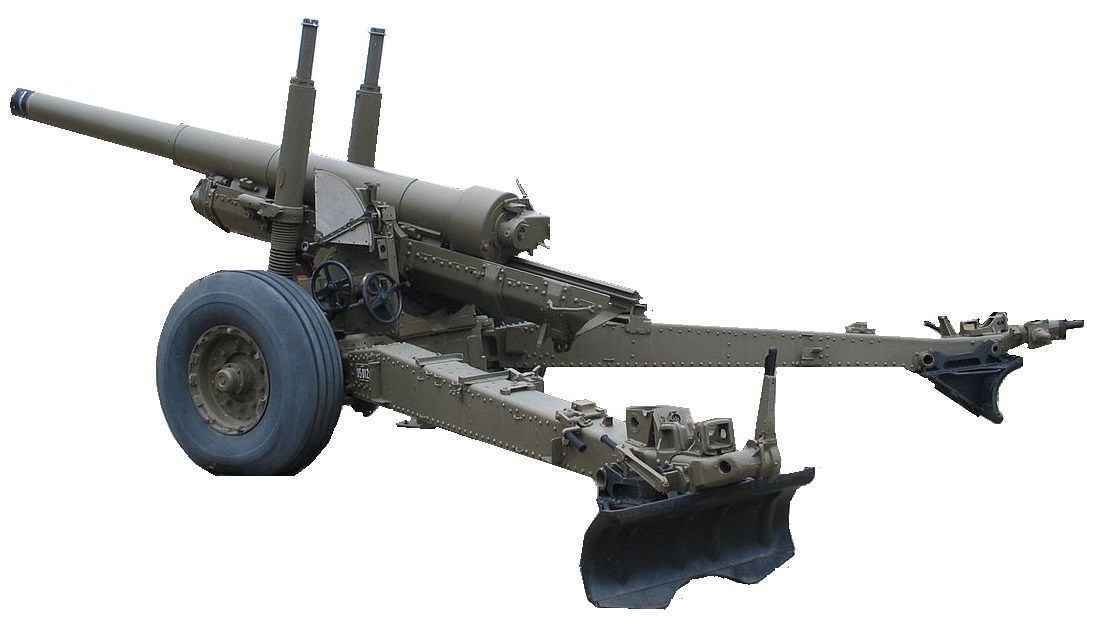
The BL 60-Pdr was introduced into service in 1905 and served with distinction during WW1. It was upgraded in 1918 to the Mk II gun on a Mk IV carriage with a longer barrel and a hydro-pneumatic recoil system giving it an increase in range from 12,300 to 15,700 yds firing a 60 lb shell.
However, by the 1930’s, the 60-pdr was growing long in the tooth and work began on a new design with a much longer range. The result was the BL 4.5-Inch Medium Gun that was adopted in 1938. The Mk I was mounted on a 60-pdr Mk IV carriage to get the new gun into service sooner. After considerable delay, the Mk II gun was introduced into service in 1941 on a new Mk I carriage that was shared with the larger BL 5.5-Inch Medium Gun which was designed to replace the BL 6-Inch 26 cwt Howitzer.
Gun Design
The Mk I gun mounted on the 60-pdr carriage was similar to the Mk II gun described here. The guns consisted of an auto-frettaged loose barrel, jacket, breech ring, removable breech bush, four lubricators and a sealing collar.
The barrel was tapered along most of its length towards the muzzle where there was a slight muzzle swell while the rear had a flange that butted up against the rear of the jacket. The jacket extended from the breech face along two thirds of the length of the barrel and was threaded at the rear to take the breech ring and at the front to take the sealing ring. About one third of the way from the front end and from the rear end of the jacket were guides fitted with gun metal bearing strips to allow it to recoil in the cradle. A gravity tank was provided above the front right guide to provide oil lubrication for the guides.
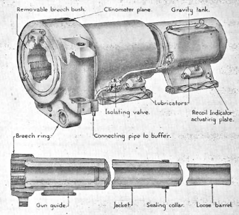
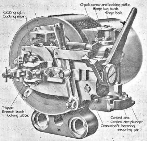
The breech bush was screwed into the rear of the breech ring to secure the barrel in place in the jacket. The breech screw was of the interrupted thread Welin type and the breech mechanism was of the single motion Asbury type. The breech was operated by pulling back the lever on the right which unlocked the breech, rotated the breech screw and then swung it out to the loading position. The gun was fired using a percussion tube that was inserted into the back of the breech after it was uncovered by moving the lock hand lever to the right. This also cocked the striker which was also provided with a T-bar cocking handle at the rear to allow it to be re-cocked if necessary. With the lock hand lever locked back in position on the left, the gun was fired using a lanyard attached to the firing trigger.
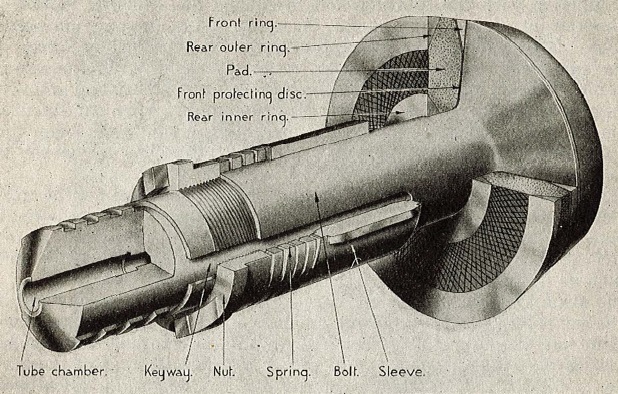
Since the gun fired bagged cartridges, obturation or breech sealing was accomplished using a mushroom headed axial vent that fitted into the front of the breech screw. This included a chamber at the back for the percussion tube that fired through the centre of the axial vent to set off the cartridge. The mushroom head was fitted with an obturator pad on the back that was pressed into the coned rear of the barrel when the breech was closed. As the gun fired, the chamber pressure forced the axial vent backwards compressing the obturator pad further against the sides of the chamber fully sealing it.
The gun was fitted with a quick-loading gear to enable the gun to be quickly lowered to the loading position and afterwards raised quickly to the firing position. This was done using a hand lever on the right-hand side of the cradle as shown below. The quick-loading gear was operated by raising the lever which withdrew the left plunger locking the cradle to the elevating arc and allowed the gun to be lowered to the loading position at which point the cradle was locked by the right plunger to the saddle. After loading, the lever was lowered withdrawing the right plunger and enabling the gun to be raised to the firing position with the left plunger then locking the cradle back to the elevating arc.
Recoil Mechanism
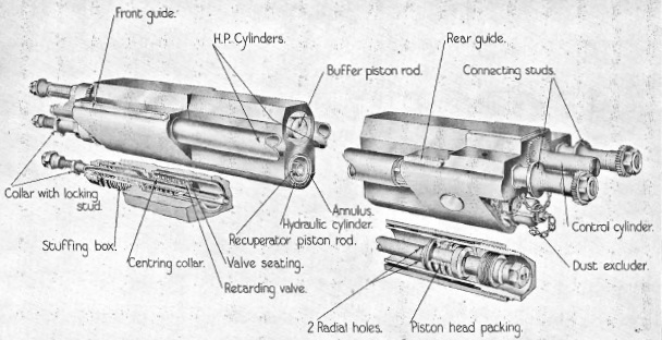
The gun recoiled in the cradle that was fitted with guide ways and trunnions. The recoil system comprised a hydraulic buffer and hydro-pneumatic recuperator contained in a cylinder block that was attached to the breech ring and recoiled with the gun. Four longitudinal cylinders were contained in the cylinder block: the upper one was the hydraulic buffer; the lower one the oil cylinder for the recuperator; and the two on either side were the high pressure (HP) cylinders for the recuperator.

The buffer piston was forged as one piece with the piston rod which was extended at the rear to form a pointed control rod. The front of the piston rod was attached to the front of the cradle. The piston had two ports in it and, as the gun recoiled, the oil in front of the piston was forced through these ports absorbing the recoil energy. However, immediately behind the piston was a rotating valve with two shaped ports in it that was keyed into two spiral grooves on the inside surface of the buffer cylinder such that the valve rotated as the gun recoiled. Although the ports in the piston and rotating valve were aligned at the start of recoil, after a certain distance, the rotation of the valve closed off the passage of oil through the piston and brought the recoil to an end.
The gun was fitted with a cut-off gear on the right of the cradle consisting of a trunnion link, actuating rod and gear mechanism at the front of the cradle that caused the buffer piston rod to rotate as the gun was elevated. The effect of this was to change the point at which the rotating valve brought the recoil to an end. When the gun was horizontal, the recoil length was 54 inches but reduced to 30 inches at the maximum elevation of 45 degrees to prevent the breech from hitting the ground.
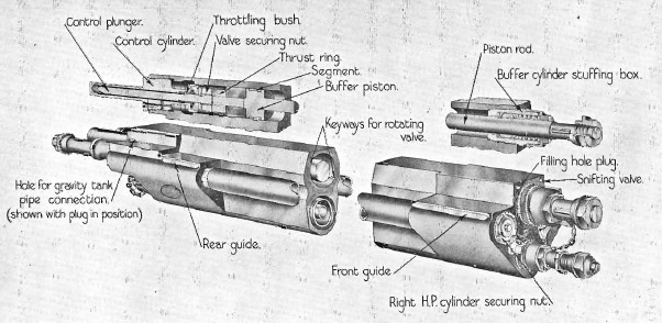
The recuperator hydraulic cylinder housed a piston on the end of a rod attached to the front of the cradle with the front of the cylinder filled with oil. As the gun recoiled, the oil was forced out of the front of the cylinder into the annular space around it and then into the rear of the two HP cylinders. At the front of the liquid cylinder was a retarding valve that fully opened during recoil but closed to slow down the run-out of the gun by restricting the return of the oil to small holes in the valve. The oil entering the back of the HP cylinders compressed the air in it so that, when the recoil ended, air pressure then forced oil back into the recuperator hydraulic cylinder which, in turn, ran-out the gun. Towards the end of the run-out, the control rod in the buffer entered a a narrow control cylinder filled with oil that had to be displaced bringing the gun to a gentle stop. The recuperator HP cylinders were pressurised to 800 lb in order to keep the gun fully run-out at all elevation angles.
Carriage Mk I
The Mk I carriage was of the split trail type consisting of two legs made of plates with an inverted U structure. The legs pivoted on the front hinge bracket and at the rear end provided the means for attaching the spades which were removed and mounted on top of the trail legs for during transport. The front of the hinge bracket supported the axle tree on which were mounted pneumatic wheels with drum brakes.

The gun cradle pivoted on the saddle shown below. This in turn pivoted on the hinge bracket and provided the means for traversing the gun. This was done using a toothed traversing arc on the hinge bracket engaged by a worm gear operated by a traversing hand wheel mounted on the left rear of the saddle. This mechanism provided up to 30 degrees of traverse to the left or right.

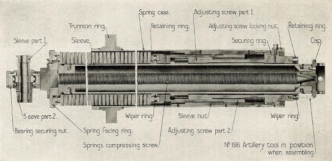
The gun was elevated by means of an elevating arc attached to the left-hand gun trunnion operated via a pinion and worm gear by a hand wheel on the left of the saddle. However, since the centre of gravity of the gun was a long way forward of the gun trunnions, the gun had to make use of a balancing gear. As shown below, this consisted of two spring compressors or struts situated either side hinged on the front of the cradle. Essentially, the gun cradle was attached to the spring case on each strut which was able to slide up or down on sleeves projecting above them with the springs supporting the weight of the gun. The spring tension could be adjusted to make sure the gun was fully balanced. The springs were normally protected by collapsible leather covers.
The gun was normally transported behind a AEC Matador 4 × 4 medium artillery tractor and did not use a separate limber.
Gun Sights
The sight supporting bracket was bolted to the end of the left-hand trunnion and therefore elevated with the gun. The sights were reciprocating which means that they were able to compensate for the carriage wheels not being level. This was normally the case and resulted in the vertical plane through the gun being rotated in azimuth in the direction of the lowest wheel – if not compensated, this would have resulted in the gun shooting to the left which would become worse at the higher elevation angles. To compensate for the wheel tilt, an oscillating bracket was mounted on the supporting bracket that could be tilted sideways by up to 10 degrees to the left or right about an axis parallel to the gun. In practice, the cross-levelling screw was used to adjust the oscillating bracket until the cross level bubble was level at which point the bracket and sights were then in the same vertical plane as the gun.
The gun used a No. 7 dial sight and a sight clinometer both of which were mounted on brackets fixed to the range scale plate which was pivoted about its centre on the oscillating bracket in order to alter the elevation of the sights. The range plate was engraved with three sets of curves graduated in 100 yds steps for Charge 1, 2 & 3. Charge 1 was graduated from 0-12,000 yds; Charge 2 was graduated from 600-16,000 yds; Charge 3 was graduated from 600-20,000 yds. The edge of the plate was graduated in degrees from 0-45 degrees in 10 minute intervals.
A reader arm was used to set the tangent elevation required for a given range and charge. This was pivoted at the lower front edge of the range scale and was provided with 3 muzzle velocity (MV) readers known as A, B & C, one for each of the 3 charges. The MV corrector strip on the arm was graduated from 1,000-2,400 fps in multiples of 10 fps with red lines engraved at 1,250, 1,750 and 2,250 fps, which were the normal MV’s for the 3 charges. The end of the MV reader arm was fitted with a hand wheel and worm gear that engaged in the teeth around the outside of the range scale plate. For the given charge, the hand wheel was turned to select the required range. The indicated tangent elevation corresponding to the selected range was applied to both the range scale plate and the sights by a motion link that connected the end of the reader arm with the oscillating bracket. This was such that when the sights were given a particular tangent elevation, the reader arm moved through twice this angle on the range scale plate – this meant that 45 degrees of tangent elevation change required 90 degrees of movement of the reader arm.
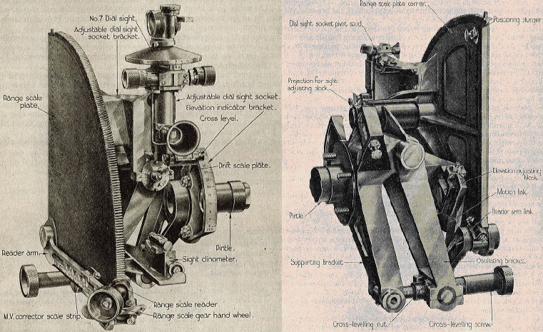
The gun was only used for indirect fire and was therefore not fitted with open sights for direct fire. Laying the gun for elevation required the use of the Mk IV sight clinometer mounted on a bracket fixed to the range scale plate. The angle of sight was set on the clinometer which provided up to 20 degrees of elevation or depression – this was the elevation angle between the target and the horizontal plane through the gun. The tangent elevation was then set up on the sight for the required range using the range scale plate hand wheel. Once the sights were set, the gun was elevated until the clinometer bubble was level which then gave the gun the required quadrant elevation (the sum of the angle of sight and the tangent elevation).
The gun was originally fitted with a No. 7 dial sight but this would have changed to a No. 9 dial sight later in the war. These sights were panoramic and used a fixed eyepiece but allowed the sighting head to be rotated a full 360 degrees with an azimuth scale provided. In indirect laying, the target bearing was defined using maps relative to a aiming point set up for the gun. The aiming point could be a suitable feature in the landscape or set up using aiming posts and could be in front or behind the gun. To lay the gun, the required relative bearing for the target was set up for the sight and then the gun was traversed until the aiming point was centred in the sight, at which point the gun was aligned with the target.
A deflection adjustment was provided for the dial sight together with a scale indicating the angle of drift. This was provided with markings for the normal settings for Charges 1,2 & 3. This adjustment was mainly used to compensate for the drift of the shells which was a function of the muzzle velocity and tangent elevation. Drift was caused by atmospheric drag and the gyroscopic forces acting on the shells causing a rightwards drift for the right-hand spin given to the shells.
Ammunition
The gun used bagged cartridges that were loaded separately after the shell. They were fired using a ‘Tube, Vent, Percussion, .5-Inch’ inserted into the back of the breech which set off the igniter powder sewn into the base of each cartridge. Three charges were available designated Charge 1, 2 & 3 made up of different amounts of Cordite propellant producing different muzzle velocities when firing the 55 lb shell. Charge 1 produced a muzzle velocity of 1250 fps; Charge 2 a muzzle velocity of 1750 fps; and Charge 3 a muzzle velocity of 2250 fps.
The gun fired a streamlined 55 lb shell with an approximately 10 calibre radius head. The high explosive used was Amatol which was a mixture of TNT and ammonium nitrate (the name derived from ammonium nitrate and Toluene) which required an exploder behind the fuze it. The shell was used with a No. 119 direct action percussion fuze, a No. 231 percussion fuze or a No. 221 time and percussion fuze.
BL 4.5-Inch Mk II Medium Gun Specifications
- Length: 24 ft 8 inch (gun horizontal)
- Maximum Width: 8 ft 4 inch (with trail stowed)
- Height: 8 ft 7 inch (to top of spring cases)
- Wheels: 3 ft 11 inch diameter pneumatic
- Weight of Gun & Carriage: 5 ton 16 cwt 81 lb
- Length of Gun Barrel: 15 ft 7.5 inch
- Length of Bore: 15 ft 5 inch
- Bore: 4.5 inch
- Weight of Gun & Breech: 1 ton 18 cwt 7 lb
- Muzzle Velocity: 2,250 fps for Charge 3
- Maximum Range: 20,500 yds
- Trail: Split box trail
- Recoil System: hydro-pneumatic
- Maximum Recoil: 54 inch at 0° elevation and 30 inch at 45° elevation
- Rifling: Polygroove with modified plain section
- Length of Rifling: 13 ft 1 inch
- Twist: Right-hand 1 turn in 25 calibres
- Grooves: 32
- Firing Method: Percussion
- Elevation: -5° to +45°
- Traverse: -30° left to +30° right
![]()