

The 6-Inch BL 30 cwt Howitzer was introduced in 1896 and was used in the 2nd Boer War (1899-1902) firing a 122 lb high explosive shell. However, its maximum range of 5,000 yds was found to be inadequate and, in 1900, a lighter 100 lb shell was developed increasing the maximum range to 7,400 yds. It was the only heavy ordnance available to the siege batteries of the Royal Garrison Artillery at the outbreak of WW1 until replaced by the more modern BL 6-Inch 26 cwt Howitzer from 1915.
The main limitations of the 6-Inch BL 30 cwt Howitzer were its relatively primitive recoil system that was split between the gun and the carriage, and its limited elevation of only 35 degree on the wheeled travelling carriage. However, it could also be deployed on a fixed siege mounting that allowed much greater elevation angles although this mounting was probably never used in the field. On the siege mounting, this gun was a proper howitzer but, on the travelling carriage on which it was normally deployed, it had to be regarded as a heavy field gun.
 Gun Design
The gun consisted of an A and B tube, breech bush, jacket, breech ring and sight ring. The B-tube was shrunk over the rifled A-tube and secured in position by shoulders and the breech bush that was screwed into the B-tube from the rear. The jacket was shrunk over the B-tube and held in position by shoulders and a screwed ring at the rear. The breech ring was screwed over the rear of the jacket and included lugs for attachment of the hydraulic buffers and the breech fittings. A sight ring was shrunk over the B-tube in front of the jacket to mount the fore sight(s).
Longitudinal projections were included either side of the jacket to act as guides for the gun inside the cradle. The Mk I* differed from the Mk I in having the chamber slightly enlarged and the length of rifling reduced as a consequence.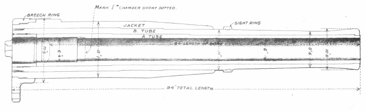
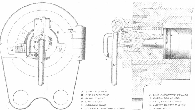
The gun was fitted with a ‘three motion breech mechanism’ and interrupted thread breech screw. The first motion was to raise the cam lever that unlocked the breech mechanism. The second motion was to rotate the breech screw with the lever. The third motion was to swing the breech screw clear to enable the next round to be loaded.
The howitzer used bagged cartridges that made the gun a breech loader rather than a quick firer in British parlance. Obturation or sealing of the breech was achieved using the mushroom headed axial T-vent. The mushroom head had a sealing ring behind it so that, when the breech was closed, the seal was pressed into the coned rear of the chamber. When the next cartridge was fired, this forced the mushroom T-vent backwards, further pressing the obturator seal against the sides of the chamber and fully sealing it.
The bagged cartridges had igniter pads sewn into the rear that were ignited using T-tubes inserted into the rear of the axial T-vent. The T-tubes consisted of a cartridge filled with a gunpowder mixture that was ignited by a cross tube containing a friction igniter operated by a lanyard.
Recoil System
The gun recoiled 18 inches inside the cradle which had cylindrical openings in the lower part to take the two hydraulic buffers. Each buffer consisted of a cylinder (A) filled with oil and fixed to the cradle inside of which was a piston (F) connected to a breech lug via a rod (G). This rod was extended in front of the piston (H) and had a flange (M) on the end that bore on the front of a recuperator spring. As the gun recoiled, the pistons were pulled backwards and oil that had to flow past the pistons providing resistance to their movement and therefore absorbing recoil energy. At the same time, the front ends of the piston rods compressed the recuperator springs.
The operation was slightly more complicated than this because the front of each buffer cylinder was fitted with a floating piston (J) with a flange at the front end that bore on the back of each recuperator spring. When the gun recoiled the larger diameter of the front part of the rod compared with the rear part caused the oil passing the piston to force the floating piston forwards compressing the recuperator spring even further. Once the recoil had been brought to an end, the recuperator springs forced the gun forward again into battery. The reason for the floating pistons was to bring the gun to a gentle stop – in later, more sophisticated forms of recoil mechanism, this function was performed by a control rod inside the hydraulic buffer.
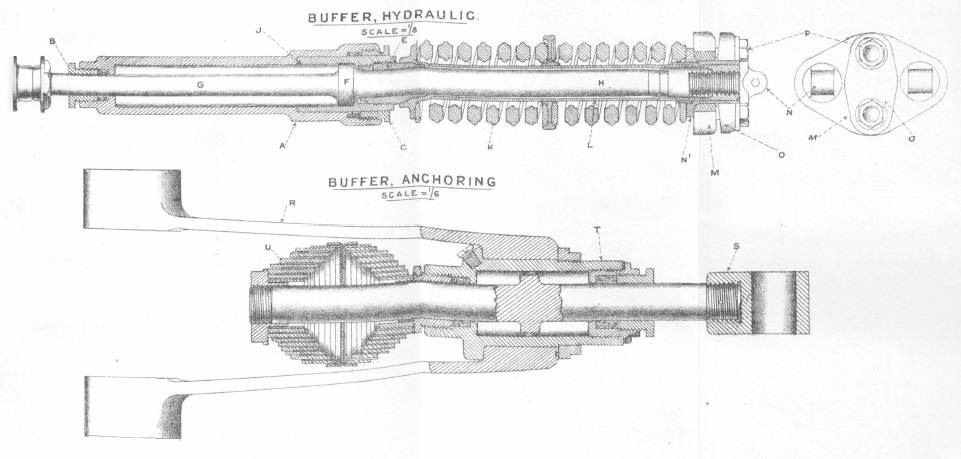
The hydraulic buffers were not able to absorb all the recoil energy which would have required 40-50 inches of recoil length. The gun was therefore designed to make use of an anchoring buffer that was connected to the axle tree by a stay (R) whose other end was attached to the radial arm of a large cast pivot plate bolted to a platform made up of two layers of wooden planks as shown below. The anchoring buffer consisted of an hydraulic oil filled cylinder (T) containing a piston on a rod attached to the crosshead (S). During recoil, the stay moved backwards with the carriage resulting in the piston moving forward through the oil which helped to absorb some of the recoil energy. At the same time, a flange at the other end of the piston rod compressed a volute spring. At the end of the recoil, the spring then pushed the carriage back giving a maximum recoil distance for the carriage of 5 inches. However, by the time of WW1, contemporary films seemed to show this device was no longer in use resulting in the carriage recoiling back some distance every time the gun was fired.
Carriage
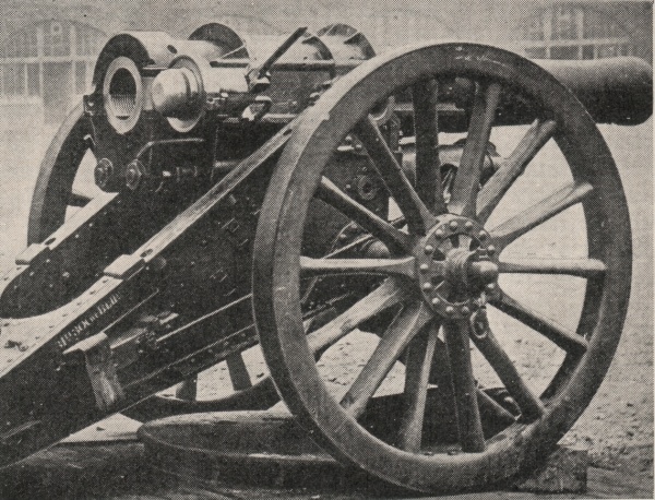
The travelling carriage was of box construction with two side plates, top and bottom plates, transoms and a towing eye. Brackets were riveted to the carriage to hold the gun trunnions and the axle tree. The carriage was fitted with standard 5 foot diameter wood spoked wheels with steel tyres. The carriage was equipped with brake arms behind each wheel operated by a hand wheel on the front right of the carriage. The gun was normally towed using horses behind a two wheeled limber with the limber used to store spares and tools.
The gun was elevated by means of a hand wheel on the left of the carriage that engaged via a worm gear with an elevating arc attached to the left-hand side of the cradle. This provided up to 35 degrees of elevation and 10 degrees of depression.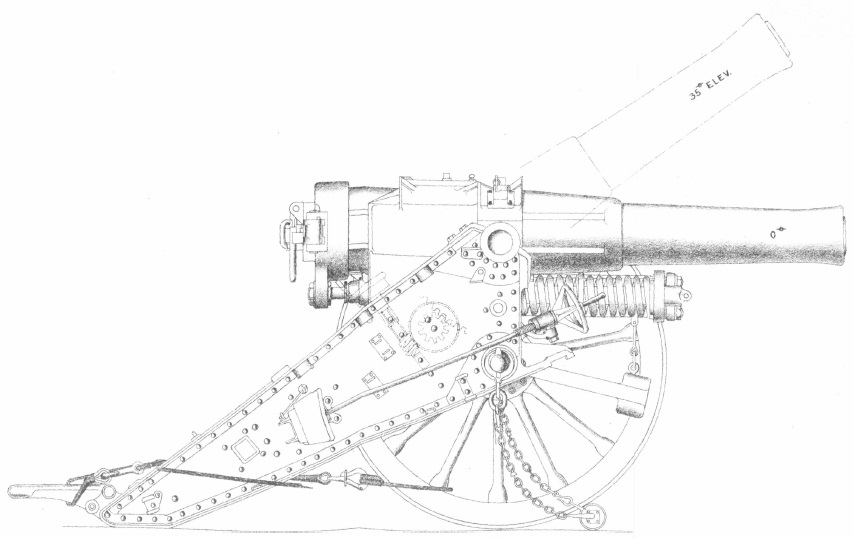
The gun was also designed to be operated on a fixed siege mounting that turned it into a true howitzer providing elevation angles in the range 35 to 70 degrees. The siege mounting made use of the travelling carriages with the wheels removed to provide a bed for the howitzer. A top carriage was then bolted on to provide brackets for the gun trunnions.
The siege mounting probably made a lot of sense when the gun was first introduced in 1896 but, by the start of WW1, the range of the gun was too limited for it to be operated in this way. Without the mobility provided by the travelling carriage, it would probably not have survived very long in the artillery counter battery environment that it would have found itself in at the start of this war. 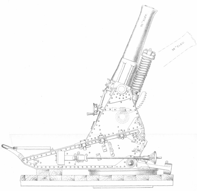
Gun Sights
Elevation was set on the howitzer using a field clinometer mounted on a plane on the rear portion of the jacket. Range tables would have been used to determine the quadrant elevation required for a particular range.
The howitzer was fitted with cross-bar sights on each side of the gun. The fore and rear sights were very similar in design to enable both front and reverse laying of the gun. Reverse laying was used in the early days of the gun before dial sights were introduced for indirect laying and enabled the gun to be laid using aiming posts set up behind the howitzer.
The rear cross-bar sights were fitted into sockets on either side of the breech ring. They were provided with a vertical bar graduated from 0-10 degrees adjusted using a clamp and a reversible cross-bar graduated from 0-6 degrees in deflection. A sliding leaf was mounted on the cross-bar with a notch in it for forward laying and and cross wires for reverse laying. By reversing the cross-bar, the sight could be used to provide both left or right deflections.
The fore sights were fitted to the sight ring on the gun and were fitted with a half cross-bar with a moveable leaf similar to the back sights. The cross-bar was not reversible and so the right-hand sight only provided right deflection adjustment and the left-hand sight only provided left deflection, both from 0-6 degrees. The fore sights had a point for use in forward laying and a notch and key hole for reverse laying.
The cross-bar sights had to be specially designed to survive the recoil of the gun since they were attached to it.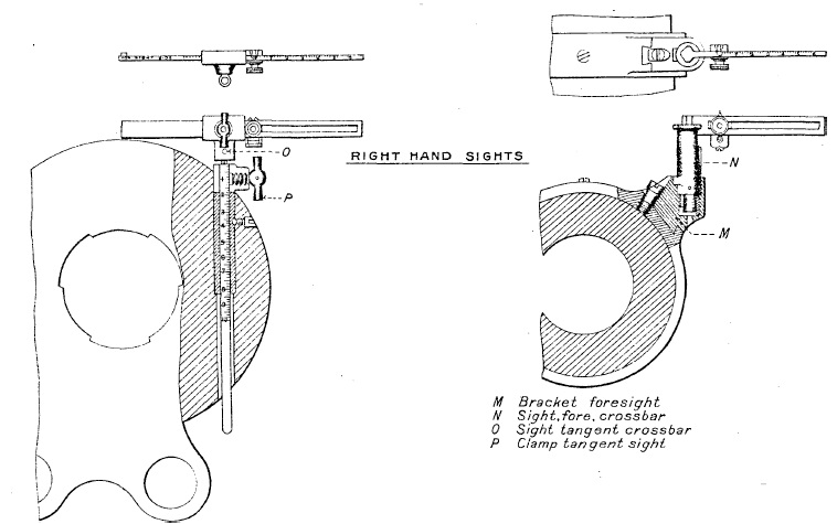
From about 1906, the howitzer was also fitted with a No. 1 dial sight for indirect laying as shown below mounted in a socket fixed to the front of the gun cradle on either side. In indirect gun laying, the required target bearing was defined by a plotting officer relative to an aiming point set up for the gun. This could be a suitable feature on the landscape identified on a map or it could be an aiming post set up in the ground some distance from the gun. The No. 1 dial sight consisted of a sight bar on a horizontally rotating table graduated in degrees that was used to set the required bearing for the gun relative to the aiming point.
The dial sight was hinged on the mounting post to allow it to be tilted sideways to compensate for the carriage wheels not being level, and tilted backwards or forwards to compensate for the elevation of the gun.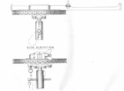
The No. 1 dial sight was very basic in its capability and was replaced in 1910 by the No. 4 dial sight. This made use of a No. 2 sighting telescope and was mounted on a carrier that provided cross levelling using an adjustment screw and levelling in the elevation plane using an elevation indicator drum and spirit level.
However, like the No. 1 dial sight, it was still a basic sight and required the operator to move around the sight to be able to observe the gun’s aiming point in the telescope if this was behind the gun. The carrier also included a deflection adjustment via a deflection scale.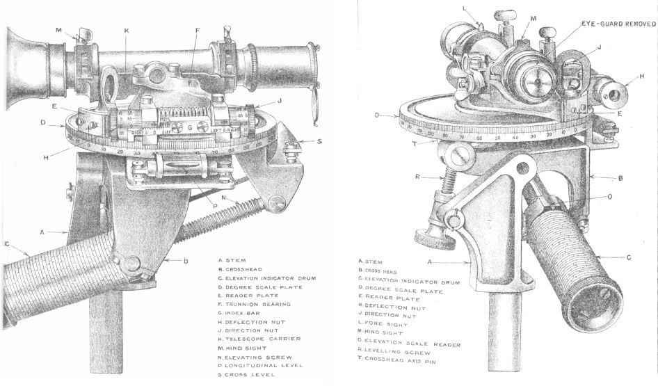
Ammunition
The gun fired shells using bagged cartridges filled with Cordite. Each bag contained igniter pads sewn into its base. These were set off by the friction T-tube inserted into the back of the breech axial T-vent.
The gun fired three types of shell: Lyddite, shrapnel and star. The original heavy Lyddite shell had a 2 calibre radius head and weighed 122 lb filled with Lyddite. It was normally fitted with a direct action No. 1 fuze. However, to increase the gun’s range a light Lyddite shell with a shorter length was introduced that weighed only 100 lb.
The shrapnel shell was filled with metal balls and was fitted with a No. 54 or 62 time and percussion fuze. These fuzes ignited powder in a central tube in the shell conveying the flash to the gun powder bursting charge in the base. This blew off the separate front of the shell and ejected the shrapnel balls at high speed towards the ground. The different marks of the shrapnel shell used shell cases of various thicknesses and contained different numbers of shrapnel balls, ranging from about 255 to 903. The shrapnel shells weighed 100 ib.
The star shell was fitted with a No. 25 time fuze set to burn for 15 seconds. The shell contained 12 ‘stars’ that were ejected out of the front of the shell by a bursting charge in the base. The fuze ignited the powder in the central tube that set off the bursting charge but was also perforated along its length to ignite the ‘stars’. The star shell weighed 57 lb.

Epitaph
The 6-Inch BL 30 cwt Howitzer was a bit of a misnomer because it was deployed in both the 2nd Boer War and in WW1 on a travelling carriage with a maximum elevation of only 35 degrees making it a heavy field gun rather than a howitzer. It also suffered from being a hybrid design developed in the mid 1890’s between the earlier field guns having no recoil system and the field guns developed in the early part of the twentieth century equipped with a fully effective recoil system. This also applied to the sights used that started as basic cross-bar sights for direct fire and progressed to only a rudimentary dial sight at the start of WW1.
The net result of these design features was a heavy field gun that was lacking in range and, because of its limited recoil system in particular, limited its accuracy when performing its primary role of counter battery fire and of attacking field fortifications. All these limitations were overcome with its replacement, at least with regular army units, by the BL 6-Inch 26 cwt Howitzer in 1915.
6-InchBL 30 cwt Howitzer Specifications
- Length: 13 ft 4 inch
- Maximum Width: 6 ft 5 inch
- Wheels: 5 ft diameter
- Weight of Gun & Carriage: 69 cwt 92 lb
- Length of Gun: 7 ft 10 inch
- Length of Bore: 7 ft
- Bore: 6 inch
- Weight of Gun & Breech: 28 cwt 89 lb
- Muzzle Velocity: 777 fps heavy shell; 858 fps light shell
- Maximum Range: 5,000 yds heavy shell; 7,400 yds light shell
- Trail: Box
- Recoil System: hydro-spring
- Maximum Recoil: 18 inch gun + 5 inch carriage
- Rifling: Polygroove with modified plain section
- Length of Rifling: 6 ft 3 inch (Mk I); 6 ft 1 inch (Mk I*)
- Twist: Right-hand 1 turn in 15 calibres
- Grooves: 24
- Firing Method: Friction T-tube
- Elevation: -10° to +35°
- Traverse: By movement of trail only
![]()