

The BL 8-Inch Howitzer Mks I-V were improvised designs developed at the start of WW1 for a heavy mobile howitzer that made use of bored out and shortened naval guns. They performed well in action but had relatively short range and were very heavy.
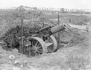
In 1915, Vickers developed an improved design, the Mk VI, based on their BL 6-Inch 26 cwt Howitzer. The 8-inch Mk VI was used from 1916 by the siege batteries of the Royal Garrison Artillery and served a similar role to the BL 9.2-inch howitzer but with a faster rate of fire and much greater mobility. The BL 8-Inch Howitzer gun went through Mks VI-VIII and the carriage went through Mks VI- VII as described below.
The gun was also used by the US Expeditionary Force during WW1 and was still being used at the start of WW2 with pneumatic tyres fitted. However, by then, its range was considered inadequate and most were converted along with others donated by the United States into BL 7.2-Inch Howitzers with a range of 16.9 km.
Gun Design
The Mk VI gun consisted of a rifled A-tube, jacket, breech bush, rear guide ring and front guide ring. The jacket was shrunk on to the A-tube and extended the full length of the gun with the breech bush screwed into the rear. The rear guide ring was shrunk over the rear part of the jacket and included two projections on the underside to serves as guides for the gun in the cradle. The front guide ring was shrunk on to the jacket and also had projections to act as guides for the gun in the cradle. The length of the bore was 14.7 calibres.
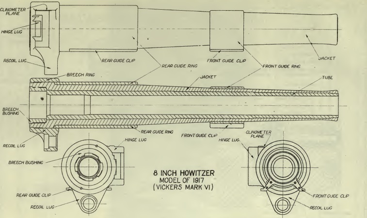
The problem with the Mark VI gun was its mediocre range which prompted a redesign in June 1916 resulting in the Mk VII. This featured a lengthened bore of 17.3 calibres. It also included a change from built-up construction to wire construction with layers of steel wire tightly wrapped around the rear part of the A-tube with the jacket then struck over the wire and the remainder of the A-tube. The Mk VII* differed from the Mk VII is having a longer chamber of smaller diameter. The Mk VII** had a shoulder formed on the exterior of the jacket to strengthen it just in front of the chamber. The Mk VIII was similar to the Mk VII** but with a thicker A-tube. The net effect of the changes from Mk VI to Mk VII gun was an increase in maximum range from 10,745 yds to 12,300 yds.
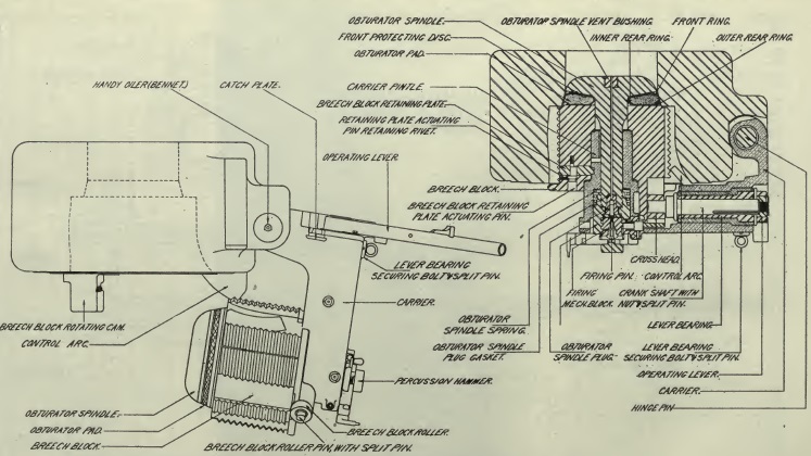
The breech was a Asbury single motion type with Welin type breech screw. The breech was operated by a lever on the right. When pulled backwards, this unlocked the breech screw and then swung it clear to the right to allow the next round to be loaded. The breech screw was fitted with a mushroom headed axial vent that incorporated an obturator pad behind the mushroom for use with bagged cartridges. When the breech was closed, the obturator pad was forced against the coned rear of the breech. When the loaded cartridge was fired, the chamber pressure pushed the axial vent backwards which, in turn, pushed the obturator pad hard against the sides of the chamber fully sealing it. The cartridge was fired using a percussion lock and ‘Tube, Percussion, S.A. Cartridge’ inserted into the back of the axial vent. The cartridges included igniter pads of gunpowder sewn into pockets at the rear that were ignited by the flash from the percussion cartridge traveling down the hole in the axial vent.
Recoil Mechanism
The recoil mechanism consisted of a hydraulic buffer to absorb the recoil forces and a hydro-pneumatic recuperator to return the gun to battery. The recoil system was contained in a cylinder block that was connected to a lug under the breech ring and recoiled with the gun in the cradle. There were 5 cylinders in the cylinder block: the centre one formed the hydraulic buffer; the two lower ones on either side formed the liquid (oil) cylinders for the recuperator; and the two upper ones on either side formed the high pressure (HP) air cylinders for the recuperator.
The hydraulic cylinder was filled with oil and contained a piston on the end of a rod fixed to the front of the cradle. As the gun recoiled and the hydraulic cylinder was pulled backwards, the oil in front of the piston had to flow through small ports in the piston restricting its flow rate and therefore absorbing the recoil energy. Immediately behind the piston was a rotating valve that had similar ports to those in the piston. The rotating valve was keyed into a pair of spiral grooves on the inside surface of the buffer cylinder that caused it to rotate when the gun recoils. At the start of the recoil, the two sets of ports were aligned to produce maximum oil flow rate through the piston but, as the rotating valve rotated, a point was reached where the flow of oil was cut off and the recoil was ended. Like most howitzers, the gun was fitted with a cut-off gear that translated rotation of the right-hand gun trunnion via an actuating rod to rotation of the hydraulic piston rod. This had the effect of shortening the length of recoil as the gun was elevated in order to stop the breech hitting the trail or the ground. The recoil varied from 60 inches when the gun was horizontal reducing to 24 inches when the gun was elevated to 50 degrees.
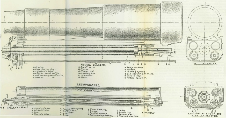
The howitzer used two pairs of liquid and high pressure cylinders on either side of the cylinder block that were interconnected by passages to equalise the pressures generated. The liquid cylinders were connected to the cylinder block at the rear but were surrounded by an annular space filled with oil that was connected to the rear of the corresponding HP cylinder. The cylinders were referred to as being rams. Inside the rams was a piston connected via a rod to the front of the cradle such that, when the gun recoiled, the piston remained stationary and the rams moved backwards with the gun. As the gun recoiled, the piston forced the oil in front of it into the annular space around the rams and then into the rear of the HP cylinders compressing the air there.
On the front of the rams was a throttle valve that opened during recoil to allow the free passage of oil. After the recoil had been brought to a stop, the compressed air in the HP cylinder then forced the oil back into the rams at the same time returning the gun to battery. While this was happening the throttle valves closed and the oil then had to pass through small holes in them controlling how fast the gun returned to battery. The end of the hydraulic buffer rod behind the piston was also formed into a control rod that entered a narrow cylinder filled with oil as the gun returned to battery helping to bring it to a gentle stop. The HP cylinders were normally pressurised to the order of 700 psi to keep the gun run out when it was elevated.
The recuperator design for the howitzer was a little unusual and, although it was based on the 6-inch 26 cwt howitzer design, it did not feature a floating piston in the HP cylinders to separate the oil from the air. Despite this, the recoil system appeared to have worked reliably in practice.
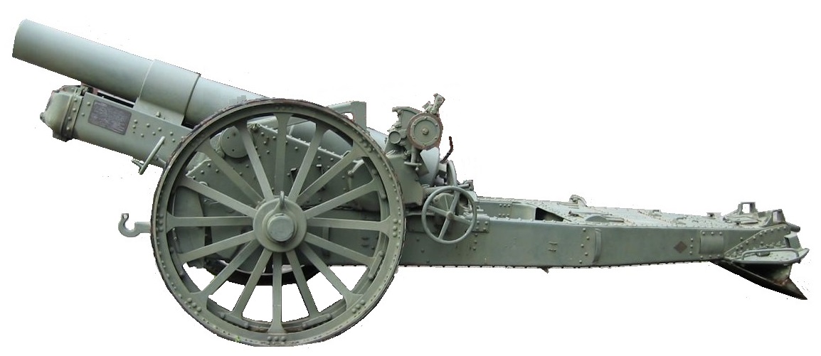
Mk VI Carriage
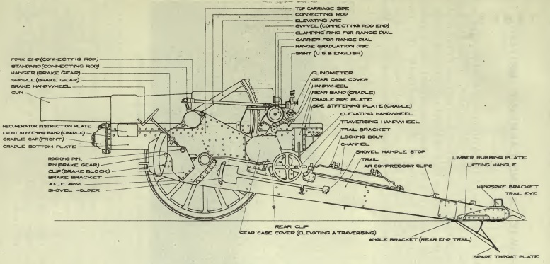
The Mk VI carriage was designed to allow the howitzer to be fired at elevation angles from 0 degrees to 50 degrees. The gun recoiled in the cradle that was fitted with trunnions to allow it to pivot on the saddle. The saddle consisted of two side pieces connected by a curved transom at the front and pivoted on the front of the trail to provide up to 4 degrees of traverse to the left of the right. A traversing hand wheel was provided on the left-hand side of the trail.
The trail consisted of two side box section brackets joined at the front by a transom and at the rear by a top and bottom plate. The transom included a bearings for the saddle pivot. A detachable spade was fitted to the rear of the trail which also included a towing eye. A draught link was fitted to the centre of the front transom to allow it to be connected to another limber or the carriage for the firing platform.
Brackets were fitted to the front for the trail for the axle tree that was fitted with traction engine steel wheels 5 ft 6 inches in diameter and 12 inches wide. Screw brakes were fitted to each wheel operated independently by a hand wheels on either side in front of the wheels. The brake shoes acted against the inside of steel rims attached on the carriage side of each wheel.
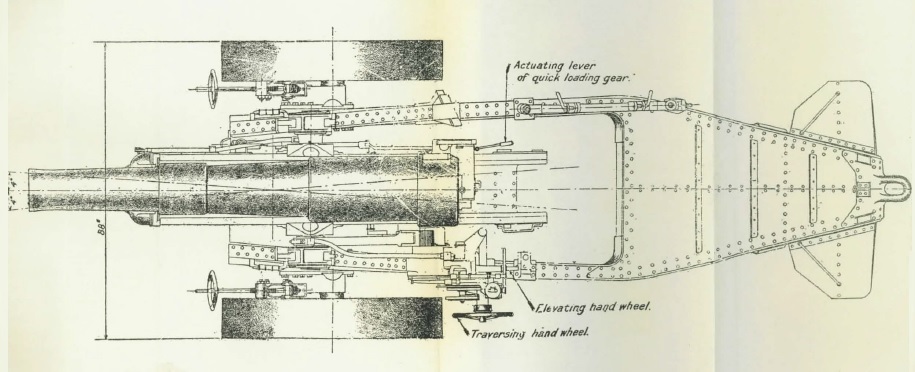
The gun was elevated via a hand wheel on the left just behind the traversing hand wheel and engaged with an elevating arc that pivoted about the left-hand gun trunnion. The howitzer was fitted with a quick-loading gear that enabled to the gun to be quickly lowered to enable the next round to be loaded. This consisted of a hand lever on the right of the gun which, when raised, disengaged the cradle from the elevating arc by withdrawing a cross-spindle. When disengaged, the lever then allowed the gun to be quickly depressed to 7.5 degrees elevation for loading at which point it was locked in position by the cross-spindle. Lowering the lever then unlocked the gun and allowed it to be raised again and locked back into the elevating arc. When the quick-loading gear was used, the sights were not disturbed.
The gun was normally fired using the spade on the back of the trail to stop it from recoiling backwards. However, it was also designed to be mounted on a firing platform as shown below that required the spade to be removed first. A curved steel track was fitted to the cross beams with holes spaced at 4 degree intervals to which the trail was locked via a pin. Using the angle brackets on either side of the trail allowed the gun to be traversed in 2 degree steps.

Mechanised towing was normally used for the gun behind its two wheeled limber used for carrying spares and tools. The firing platform was moved by re-positioning the wooden beams and then attaching an axle tree and wheels to allow it to be towed behind the gun. Two guns and limbers could be towed en-train.
![]()
Mk VII Carriage
The Mk VII carriage was designed to be used with the longer barreled Mk VII & VIII guns. The main changes involved modifications to the recoil mechanism and the use of a larger diameter buffer cylinder. It also involved a reduced maximum elevation angle of 45 degrees. The cut-off gear was modified to give a recoil length of 52 inches at 0 degrees elevation reducing to 24 inches at 45 degrees elevation.
Gun Sights
The sights were supported on a sight bracket that pivoted on the saddle some distance behind the left-hand gun trunnion to place them in a more convenient position to use. The sight bracket was rotated through the same angle as the gun via a parallel motion link with its operating arm pivoting with the end of the elevating arc on the gun trunnion.
The sights were oscillating or reciprocating to compensate for the carriage wheels not being level. This was normally the case and resulted in the vertical plane containing the gun being rotated in azimuth in the direction of the lower wheel – the greater the elevation angle, the greater was the rotation angle. To compensate for this effect, the sights were mounted on an oscillating bracket that pivoted on the sight bracket about an axis parallel to the gun. In practice, the oscillating plate was aligned with the vertical plane using the cross level bubble and adjustment screw ensuring the sights were then in the same plane as the gun therefore compensating for any tilt of the wheels.
The oscillating bracket contained a cover on the outside for the toothed range quadrant to which the sights were mounted. The range quadrant was rotated using the small hand wheel provided that also turned the range dial that was graduated from 0–50 degrees. The range quadrant supported a bracket for the sight clinometer and the tubular sight bar, or rocking bar. This had a fixed acorn fore sight and a notched back sight mounted on a bracket providing deflection from 5 degrees left to 5 degrees right.
The sight clinometer could be set to provide up to 20 degrees of elevation or 20 degrees of depression. It was used to set the angle of sight which was the difference in elevation angle between the target and the horizontal plane through the gun. In indirect fire mode, the required range was converted to a tangent elevation angle using range tables. To lay the gun, the required angle of sight was set on the clinometer and the required tangent elevation set on the range dial. The gun was then elevated until the clinometer bubble was level indicating that the required quadrant elevation angle (the sum of the angle of sight and the tangent elevation) had been set.
The carrier for the No. 7 dial sight was fixed to the range quadrant. This carrier also included the means for providing up to 10 degrees of deflection to the left or right. The required azimuth bearing for the gun was determined by a plotting officer using a map and defined as an offset angle from the gun’s aiming point. The aiming point was a clearly defined feature in the landscape which could be behind or in front of the gun. The required offset was set on the panoramic dial sight and the gun then traversed until the aiming point was centred in the sight at which point the gun had the correct target bearing.
In addition to providing a deflection adjustment, the oscillating bracket was given a fixed tilt of a few degrees to the left when the cross bubble was leveled in order to account for the drift of the shells to the right. This phenomena, often called spin drift, results from the spin axis of the shell necessarily deviating from the direction of travel at the longer ranges due to its trajectory. This results in the air resistance producing a turning moment on the shell that results in a gyroscopic rotation of the shell to the right which, because of air resistance, results in the shell drifting in the same direction.
Ammunition
The 8-inch howitzer fired high explosive (HE), common pointed and gas shells, all weighing 200 lb. It used separate bagged cartridges that included igniter patches sewn into the base. The earlier marks of the 8-inch howitzer used a choice of 4 different sizes of charge but this was increased to 6 different charges for the Mk VII. This gave the later marks of gun a range of muzzle velocities from 1300 fps to 1500 fps.
The HE shell was fitted with a No. 101 percussion fuze or No. 106 direct action percussion fuze. It originally had a 4 calibre radius head although the Mk XIV had a 2 calibre radius head. A common pointed shell with a 4 calibre radius head was also used which had a solid nose and a No. 16 percussion fuze mounted in the base.
The gas shell was similar to the HE shell and included a No. 106 percussion fuze and bursting charge in the nose.
BL 8-Inch Howitzer Specifications
- Length: 21 ft 4.5 inches for Mk VI;
- Maximum Width: 8 ft 3.9 inches
- Wheels: 6 ft 6 inches
- Weight of Gun & Carriage: 170 cwt 69 lb for Mk VI; 177 cwt 56 lb for Mk VII; 179 cwt for Mk VI
- Length of Gun Barrel: 10 ft 7.6 inches for Mk VI; 12 ft 4.3 inches for Mk VII & VIII
- Length of Bore: 9 ft 9.7 inches for Mk VI; 11 ft 6.4 inches for Mk VII & VIII
- Bore: 8 inch
- Weight of Gun & Breech: 58 cwt 56 lb for Mk VI; 67 cwt 56 lb for Mk VII; 69 cwt for Mk VIII
- Muzzle Velocity: 1300 fps for Mk VI; 1500 fps for Mk VII & VIII
- Maximum Range: 10,745 yds for Mk VI; 12,300 yds for Mk VII & VIII
- Trail: Box
- Recoil System: hydro-pneumatic
- Maximum Recoil: 60 in at 0° elevation and 24 in at 50° elevation for Mk VI gun
- Maximum Recoil: 52 in at 0° elevation and 24 in at 45° elevation for Mk VII & VII guns
- Rifling: Polygroove with modified plain section
- Length of Rifling: 8 ft 6 in for Mk VI; 8 ft 7 in for Mk VII; 8 ft 3 in for Mk VII* & VIII
- Twist: Right-hand 1 turn in 15 calibres
- Grooves: 48
- Firing Method: Percussion
- Elevation: 0° to +50° for Mk VI; 0° to +45° for Mk VII & VIII
- Traverse: -4° left to +4° right
![]()