

In the early years of the 20th Century, the French Army doctrine (Offensive à Outrance) was to rely heavily on the Canon de 75 Mle 1897 to provide the mobility and fast rate of fire they considered necessary in modern warfare. However, they also invested in the Canon de 155 Mle 1904 CTR Rimailho to provide a heavier field gun with a high rate of fire. Unfortunately, as only 104 of these were available at the outbreak of WW1, the obsolete Canon de 155 L Mle 1877 had to be bought out of retirement in order to provide enough 155 mm artillery to meet the Army’s needs.
However, by 1915, it was clear that in the type of trench warfare that had developed, the 43 kg shells fired by the 155 mm guns were too light to destroy the stronger German fortifications. The French army had the Mortier de 220 mm L Mle 1880 firing a 100 kg shell but these were obsolete short range mortars and not really suitable to the new form of warfare. Fortunately, Schneider had designed a modern version of this mortar (in 228 mm or 9 inch calibre) for Russia in 1909. Although this was not put into production, it was used as the basis for the Mortier de 220 Mle 1915 that incorporated a mobile carriage and a hydro-pneumatic recoil system for the gun. The new mortar was ordered in 1915 with the first deliveries taking place in 1916. However, problems were found with transporting the gun and a modified version, the Mortier de 220 Mle 1916, was developed to try to overcome the problems. The Mortier de 220 Mle 1915/16 served throughout WW1 and was even used at the start of WW2 by the French Army and in the years shortly afterwards.
The Germans had an equivalent mortar in WW1 in the form of the 21 cm Mörser 10/16 but the British closest equivalent was the BL 8-inch Howitzer, the difference being that the former was capable of high angle fire but the latter was not – that is basically the difference between a mortar and a howitzer. The advantage of high angle fire (> 45° elevation) was that the steeper angle at which the shells descended and hit the target was more suitable for destroying strong points. The British instead relied on the heavier 9.2-Inch BL Howitzer (maximum elevation of 55°) for this purpose although they never classified this as a mortar.

Gun Design
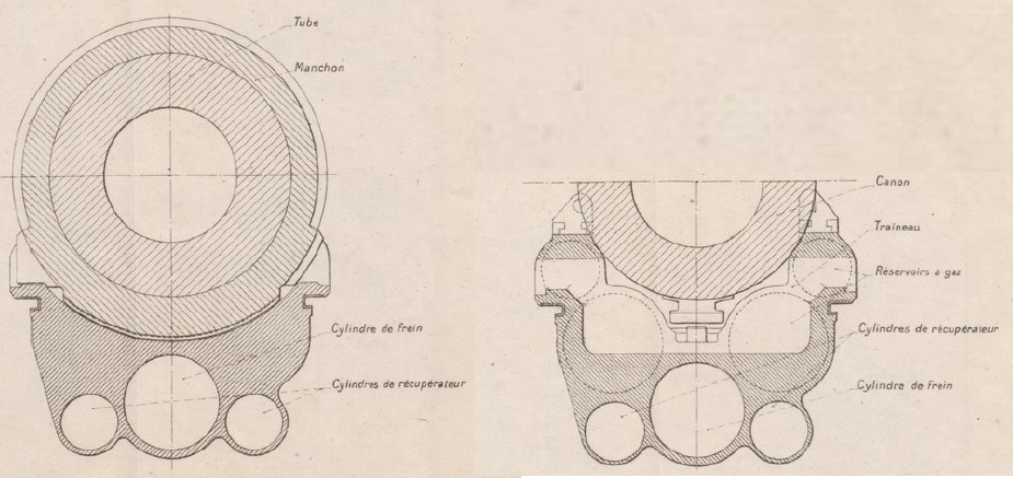
The gun was 2.278 m or 10.4 calibres and was of built-up construction as was normal during the early part of the 20th century. The gun consisted of a rifled tube with a chamber for the projectile at the rear behind which was an interrupted threaded section for the breech. A jacket (manchon) was shrunk over the rear portion of the tube with fittings to support the breech.
The gun was supported on 4 rollers to allow it to recoil smoothly on rails on top of the cradle (traineau), two on the guidance frame (frette de guidage) and two on the side of the breech. The cradle extended 1.5 m beyond the breech to allow it to support the gun throughout recoil. It was coupled to the hydraulic buffer inside the cradle via the teeth (adents) beneath the gun. The gun was fitted with a counter-weight above the breech (masse d’equilibrage) that also served as a socket for connecting to the arm of the transporting limber.
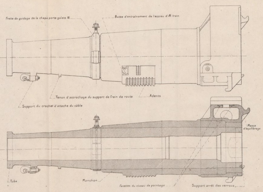
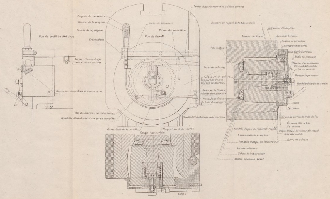
An interrupted screw breech was used with a single motion lever that, when operated, rotated the breech screw to unlock it before swinging it clear of the breech opening. The mortar used bagged cartridges with the sealing of the breech (obturation) achieved by using a mushroom shaped axial vent (tête mobile) that fitted into the front of the breech screw. Between the mushroom head and the front of the breech screw was a sealing ring such that, when the breech was closed, the seal was pressed against the tapered rear of the combustion chamber. When a charge was fired, the combustion chamber pressure pushed the axial vent slightly backwards further compressing the sealing ring against the side of the chamber completely sealing it. This widely used type of breech was invented in France by Charles de Bange in 1872.
The bagged charges were ignited using a percussion cartridge that fired through centre of the axial vent. The cartridge was set off by a striker that was hit by a hammer (marteau) at the rear of the breech that was cocked manually and released via a lanyard.
Carriage Design
The carriage consisted of a box trail with side arms in the front half that allowed space for the gun to recoil at higher elevation angles. In the original 1915 model, the carriage was fitted with 12 spoked wooden wheels with steel tyres. However, during transportation, these were found to be not strong enough and therefore a modified 1916 model was introduced with stronger wheels using 14 spokes and fitted with thick rubber tyres. A shield was mounted on the front of the trail to protect the gun crew with a hinged opening to allow for forward observation of the gun sight. The rear of the trail was provided with a hinged spade to stabilise the gun during firing which was supplemented by wheel brakes. These consisted of metal rims inward of each wheel fitted with external brake bands that were tightened by arms that were rotated about the wheel axle using a hand crank handle on the lower front right of the shield.
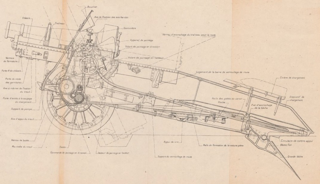
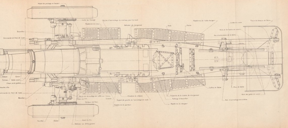
The gun pivoted on trunnions running in bearings at the top of the front of the trail with traverse provided by moving the trail sideways by up to 3 deg either side along the wheel axle. A traversing hand wheel was provided on both sides of the trail for this purpose that each rotated a screw thread inside a tube in front of the axle. This in turn moved a nut on the thread that was attached to the wheel axle resulting in the front of the trail being moved sideways along the axle.
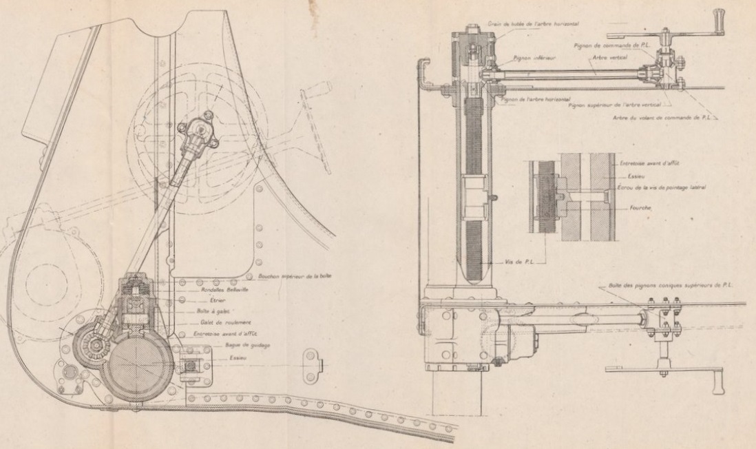
The gun was elevated by means of a pair of large toothed arcs fitted either side under the gun cradle. An elevating hand wheel was provided on the left-hand side of the carriage that rotated a pair of pinions via a gear train that meshed with the elevating arcs.
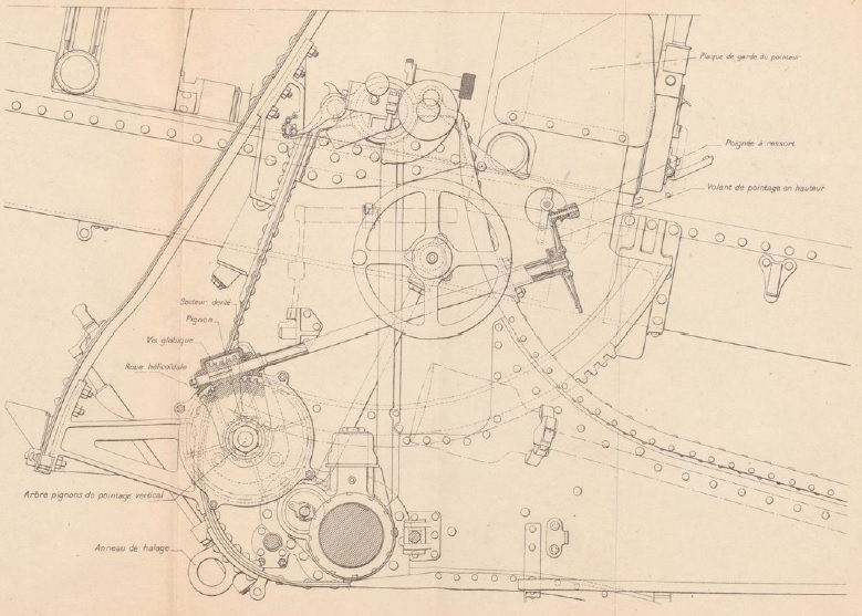
However, to load the next round, the gun had to be lowered to 10° of elevation. This was achieved by first using the loading lever (middle top below) to disconnect the cradle from the normal elevating mechanism allowing the gun to be rapidly lowered using the hand wheel on the right of the trail below the traversing hand wheel. This engaged with a second elevating arc (secteur de relevage ) via a pinion and gear train. Once loaded, the gun could be returned rapidly to the correct elevation for firing.

The trail was fitted with metal platforms on either side to allow the gun crew to stand on to facilitate shell handling, breech loading and gun laying. The trail also mounted rails that could be raised to the same height as the rear cradle extension when the gun was in its 10° loading elevation. A loading trolley (civière de chargement) was mounted on the rails and allowed a 100 kg shell to be loaded on to it at the rear of the trail and then pushed forward to load it into the breech.
Transportation
The mortar was too heavy for transporting in a single load by horse and therefore needed to be divided into two separate loads. To do this, the gun had to be winched off the carriage onto a transporting 4 wheeled carriage as shown. The remaining gun carriage itself was then transported hooked up to a 2 wheeled limber.
![]()
![]()
Recoil System
The Mortier de 220 Mle 1915/16 used a hydro-pneumatic recoil system. This was contained within the cradle (berceau) on a recoil sled (traineau) that recoiled with the gun moving along rails on either side of the cradle. The cradle extended some distance behind the breech to allow the gun to be fully supported for the full length of recoil of 1.27 m. The mortar was not equipped with a variable recoil system and, therefore, to prevent the breech hitting the ground at the higher elevation angles, it required a pit to be dug under the breech to prevent this.
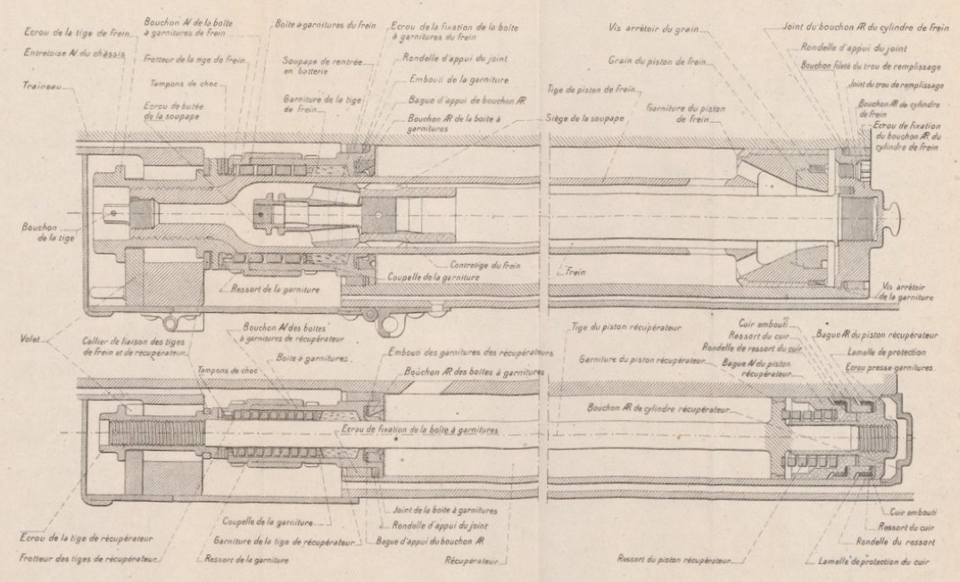
Within the recoil sled, there were 5 cylinders with 3 in the lower part with the centre one forming the hydraulic buffer (frein) and the outer ones forming the recuperator (recuperateur). At the front above these cylinders were 4 air reservoirs for the recuperator.
The hydraulic cylinder was filled with oil and contained a piston on the end of a tube attached to the front of the cradle so that, as the gun recoiled, the cylinder moved backwards while the piston stayed still. The piston contained small ports to restrict the flow of oil past it during recoil and, in so doing, absorbed most of the recoil energy helped a little by the air pressure in the recuperator. The hollow piston tube (tige de frein) was also filled with oil and contained another piston on the end of a rod (contretigre) attached to the rear of the recoil sled. The purpose of this inner hydraulic buffer was to absorb the energy generated by the recuperator in order to bring the gun to a gentle stop when it was returned to battery.
The recuperator was responsible for returning the gun to battery after the recoil ended. It consisted of two identical cylinders in the lower part of the recoil sled, that recoiled with the gun, with each containing a piston on the end of a rod fixed to the front of the cradle. As the cylinders moved backwards, the oil in front of the pistons was forced into the four air reservoirs thus compressing the air inside. Once the recoil had stopped, this increased air pressure then forced the oil back into the recuperator cylinders, forcing the cylinders forward and the gun back into battery. The ambient air pressure was maintained at 500 psi to hold the gun in the forward position.
Sights
The sights were mounted on a bracket fixed to the end of the left-hand gun trunnion and therefore elevated with the gun. The sights were reciprocating to allow them to compensate for the carriage wheels not being level, which was the norm. Ignoring spin drift and the wind, the shell trajectory will then lie in the vertical plane through the gun barrel. However, if the wheels and therefore the gun trunnions are not horizontal, this trajectory plane will be rotated away from the centre line of the gun cradle in the direction of the lowest wheel resulting in a large sighting error if uncompensated. To eliminate this effect, the sights were mounted on a reciprocating bracket that could be tilted sideways about an axis maintained parallel to the gun to put the sights back into a vertical plane parallel to that of the projectiles. This tilting was performed using the knurled knob (vis de commande de correction de d’inclinaison) and the cross-level bubble (niveau d’inclinaison) at the rear of the sight.
The required tangent elevation was set on the sight using the large knurled knob (tambur molete de l’arbre de commande) at the rear of the sight assembly that controlled the height of a toothed arc on which the actual sights were mounted- when raised, this tipped the sights forward with a tangent elevation scale provided marked in milliemes (the same as a NATO MIL with 6400 to 360 degrees). A clinometer was provided above the elevation adjustment knob consisting of a level bubble (niveau de site) and a pair of knobs to set the angle of sight from -500 to -500 milliemes . To set the gun to the required quadrant elevation to hit a target at a particular range, the angle of sight and the tangent elevation were set on the sight and then the gun was elevated until the clinometer bubble was level.

The mortar was mainly used for indirect fire where the target was not visible in the sights. However, the sights used were developed before the adoption of an effective panoramic sighting telescope (goniomètre panoramique) became available and instead used a goniometer (goniomètre) mounting a collimator on top of a rotatable column as the main sighting device. The goniometer was fixed in a socket at the top elevating arc. The collimator sight itself consisted of a rectangular hood through which the target was viewed together with a small collimator in the lower part. The collimator generated a cross-hair reticule in the field of view of the sight effectively focused at infinity. Therefore, when looking through the sight hood, the gun layer saw the target with the reticule superimposed on it with very little parallax. In use, the gun layer positioned his head about 10 inches behind the sight to use it properly.
The mortar was layed for direction using a suitable fixed aiming point that could be viewed in the sight. The offset bearing from the aiming point to the target was set on the collimator sight using the crank handle (manivelle du plateau mobile) and the fine and coarse bearing scales. The inclination of the field of view of the collimator sight could be changed using the tilt knob (molette de l’arbre d’inclinquetage). The aiming point for the sight could be chosen to be in front of the gun, to the side of it or to the rear. To enable an aiming point to be used behind the gun, the collimator sight was provided with a prism (prisme de reperage en arriere) providing a rear view past the sight.
Ammunition
The Mortier de 220 Mle 1915/16 used bagged cartridges with the choice of at least 5 charge levels giving a maximum muzzle velocity of 415 m/s. The mortar fired two type of shell: high explosive (HE) and gas. The Obus D Mle 1915 shell weighed 100.5 kg and contained about 25 kg of HE. It would have been used with a percussion fuze 24/31 Mle 1899/1915.
Mortier de 220 Mle 1915/1916 Specifications
-
- Length: 6.6 m
- Maximum Width: 2.6 m
- Wheels: Metal 1.5 m in diameter
- Weight of Gun & Carriage: 7,460 kg Mle 1915, 7,910 kg Mle 1916
- Length of Gun: 2.278 m or 10.4 calibres
- Bore: 22.0 cm
- Muzzle Velocity: 415 m/s (Obus D Mle 1915 Projectile)
- Maximum Range: 10,800 m
- Trail: Box trail
- Recoil System: Hydro-pneumatic
- Maximum Recoil: 1.27 m
- Rifling: Polygroove
- Twist: 10° corresponding to 1 turn in 17.8 calibres
- Grooves: 92
- Firing Method: Percussion
- Elevation: 10° to +65°
- Traverse: -3° left to +3° right
![]()