

The British 15-Pdr BL field gun and 5-Inch BL Howitzers used in the 2nd Boer War (1899-1902) were out-ranged by the Cruesot 155 mm siege guns used by the Boers. These were referred to as ‘Long Toms’ by the British. In order to combat these guns, Captain Percy Scott removed a pair of 4.7 inch naval guns from his ship, HMS Terrible, and mounted them on improvised wooden carriages. These guns went on to do sterling service during the war and also caught the imagination of the public at large.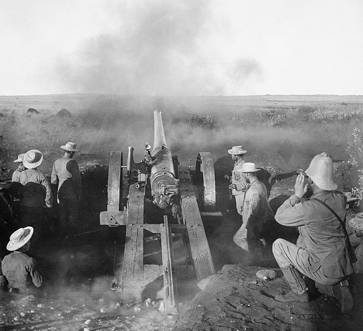
Given their success in the Boer War, many hundred of these 4.7 inch naval guns were then adopted by the Royal Garrison Artillery mounted on a more modern carriage designed at the Woolwich Arsenal or on a carriage converted from the 40-Pdr Rifled Muzzle Loader (RML). These guns were designated the 4.7-Inch QF ‘B’ on Travelling Carriages and were made by the Elswick Ordnance Company, a part of Armstrong Whitworth. The ‘B’ indicated that these guns were fitted with single motion breeches.
However, a Heavy Battery Committee had been established in 1902 and presided over by Colonel Perrott who had commanded the Siege Train in South Africa with the aim of drawing up the specifications for a future heavy field gun. They ultimately rejected the 4.7 inch gun because of its relatively light shell as well as concern over its accuracy. Their work eventually led to the adoption of the 60-Pdr BL Gun in 1905.
The new 60 pdr went to the regular units of the Royal Garrison Artillery unit and the 4.7 inch guns were relegated to the Territorial units by the start of WW1. However, well over 100 4.7 inch guns went to France in 1914 and gave good service until their barrels became too worn and started to affect their accuracy. They were withdrawn from front line service in 1917 and replaced by 60-pdrs.
Gun Design
The 4.7 inch field gun was designated a quick-firer (QF) because it not only incorporated a recoil mechanism but also used brass cartridges to provide obturation (sealing) of the breech. This allowed the gun to be re-loaded quickly without the need to swab out the breech in between rounds which was necessary for guns using bagged cartridges like the 60-pdr.
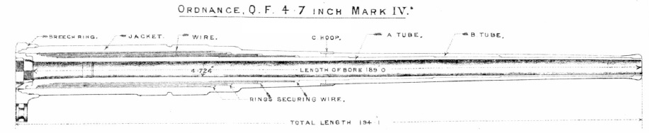
The original Mk I gun shown below was of built-up design consisting of rifled A-tune, jacket, 1B – 5B hoops, and the breech ring. The hoops were shrunk fit over the front two thirds of the A-tube and then the jacket was shrunk fit over the rear part and secured at the front end by a screwed steel ring. The breech ring was shrunk fit over the rear of the breech ring.
The gun evolved over 4 separate marks and, in Mk IV form shown, employed layers of steel wire wound tightly over the rear portion of the A-tube to provide the required tensile strength. In addition to the steel wire, the gun consisted of the jacket, breech bush, B-tube, C-hoop and breech ring.
The breech ring on all marks included lugs for the attachment of the breech mechanism and for the recoil mechanism rods. The gun was provided with two longitudinal projections on the upper and lower sides to form guides during recoil within the cradle.
The ‘B’ version of the 4.7 inch gun was fitted with a single motion breech that required one pull of the operating lever to unlock the breech screw and swing it clear of the breech opening. The breech screw consisted of three sections of interrupted thread with the rear portion cylindrical and the front part tapered to allow for clearance when the breech was opened. The breech was fitted with an extractor bolt that automatically ejected a spent cartridge when the breech was opened. The gun used brass cartridges with a percussion igniter tube (VS Tube) in the base. They were fired using a striker built into the centre of the breech screw that had first to be cocked and then triggered using lanyards.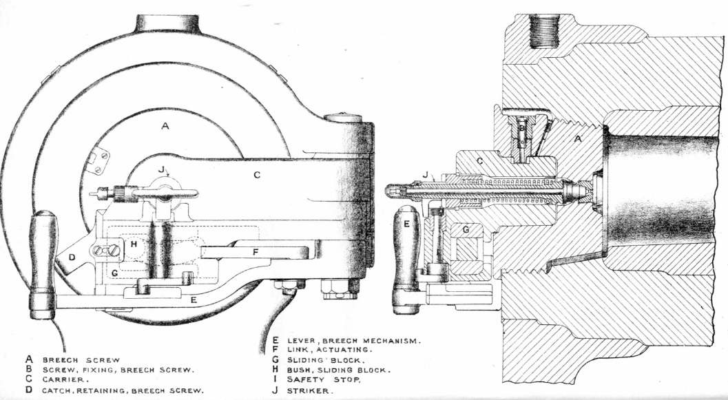
Recoil Mechanism
The gun recoiled axially in the cradle that consisted of a gunmetal casting incorporating trunnions to allow it to pivot on the carriage. A metal shield was provided to the left of the breech to protect the crew from the recoiling gun. An hydraulic buffer was mounted below the cradle with its large diameter piston rod connected to a lug under the breech. During recoil, oil had to flow past the moving piston absorbing the recoil energy. A control rod was positioned at the front of the buffer and entered a cavity in the piston rod as the gun was run out after recoil and, by having to displace oil, brought the gun to a controlled stop. Two spring cases where mounted above the cradle and were operated by rods connected to lugs above the breech. When the gun recoiled, flanges on the front of the rods compressed the run-out springs so that, when the recoil ended, they returned the gun to battery.
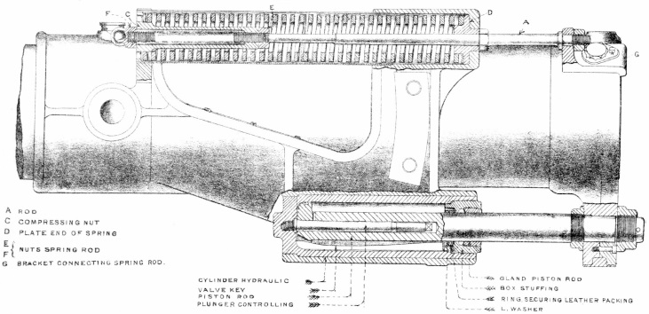
The recoil mechanism would have been adequate when used in its coastal defence gun form with fixed carriage but was very limited in field gun use with a recoil length of only 12 inches. In order to stabilise the field gun properly during firing, it had to rely on a spade mounted at the end of a telescopic spring cylinder that was hinged beneath the front transom on the carriage. The spade was attached to a spring case on the rear of the trail by means of two steel cables. During recoil, the spade dug into the ground but allowed the gun carriage to move backwards to then be rolled forward again under spring action.
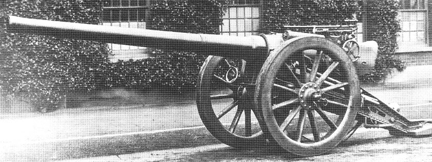
Travelling Carriage Mk I
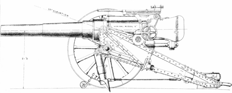
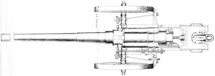
The 4.7 inch gun was mounted on to a newly built ‘Woolwich’ carriage shown below or to a carriage converted from the 40-Pdr RML Gun. Functionally, the two carriages were similar. Up to 20 degrees of elevation was possible via a hand wheel driving a worm gear and elevating arc on the left-hand side of the gun. No means for traversing the gun was provided other than by manually traversing the end of the trail.
The carriage was provided with two standard 5 foot wooden wheels. Brake shoes were provided at the rear of each wheel operated by hand wheels on the front transom. The gun was transported by hooking it to a two wheeled limber pulled by horses.
Gun Sights
The sights were mounted on a carrier fixed to the left-hand side of the cradle. A rocking bar was fitted to the carrier and pivoted horizontally by means of an elevating arc at the rear and a hand wheel. A drum was provided with separate rings for the different charges to indicate range in yards. The sight bar was mounted on the rocking bar and was provided at the rear with a deflection adjustment using a screw. The sight bar carried a fixed fore sight and notched back sight. The sight bar also included brackets to take a No. 2 sighting telescope. The sighting system was relatively primitive compared with that fitted to the other British field guns at the time and incorporated non of the refinements included in the sighting system used on the 60-pdr.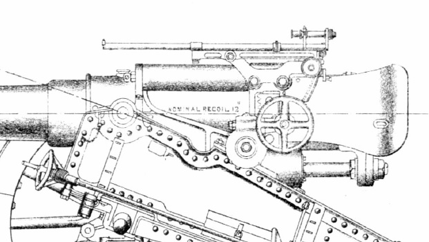
Ammunition
The cartridges were separately loaded and consisted of a brass case using a percussion vent-sealing (VS) tube in the base to set off the Cordite propellant. The common Lyddite and shrapnel shells used a Cordite charge of 5 lb 7 oz while the common iron shell used a charge of 2 lb 5 3/4 oz.
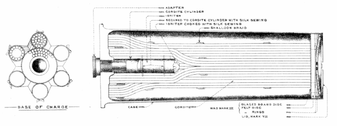
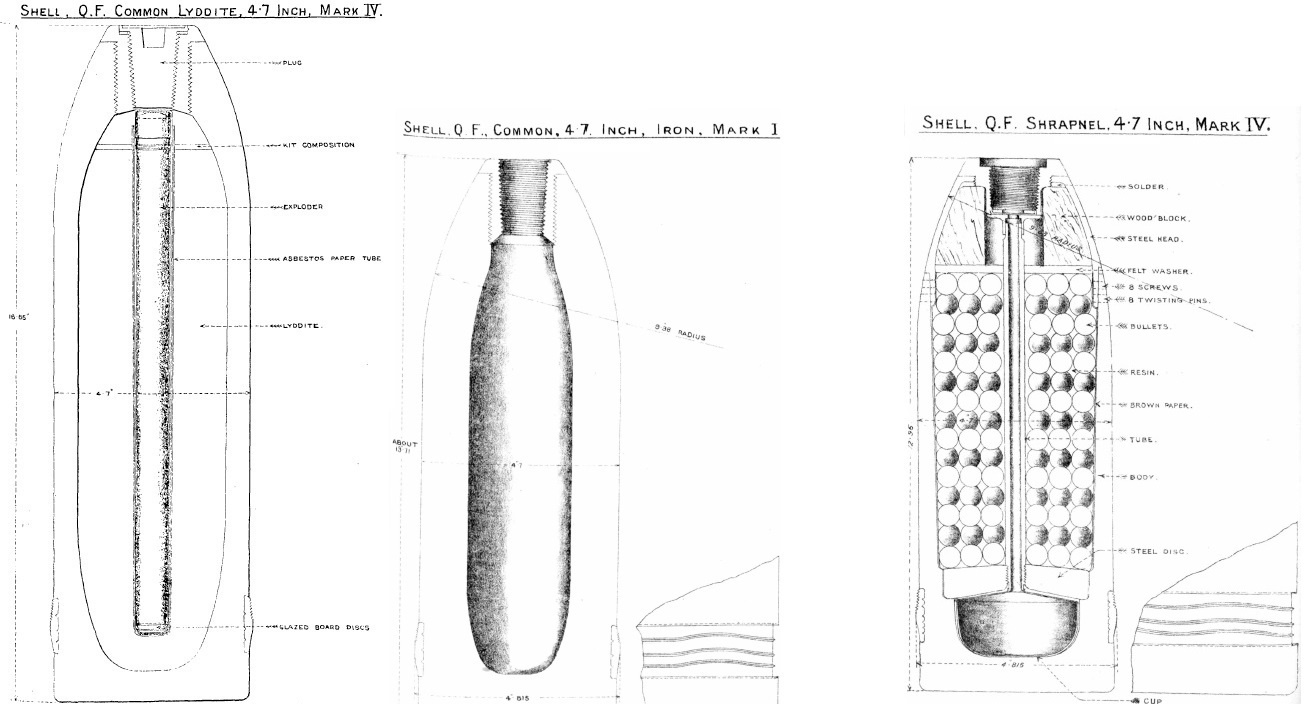
The common Lyddite shell weighed 46 lb 9 oz including the fuze and in Mk IV form was filled with 6 lb 9 oz of Lyddite and had a length of 16.65 inches. It was set off using an igniferous No. 1 DA Percussion Fuze with Cap but required a picric powder exploder to set off the Lyddite that was contained in a central 12.5 long paper cylinder.
The shrapnel shell weighed 45 lb and contained 206 mixed metal balls. In Mk IV form, it was 12.96 inches long. It was fitted with a No 54 or No. 62 Time & Percussion Fuze. When the fuze went off, it ignited gunpowder in a central tube that then set off the 4.5 oz bursting charge in the base of the shell ejecting the fuze and shrapnel balls at high speed to spray the ground in front of the shell.
The common iron shell weighed 45 lb and was filled with a bursting charge of 1 lb 8 oz of LG powder. It’s length varied between supplier but was set off using a No. 1 DA Percussion Fuze.
Epitaph
The 4.7 inch gun could be regarded as an intermediate step between the improvised naval gun used with considerable success by the Naval Brigade in the Boer War and the later purpose designed 60-Pdr BL Gun adopted in 1905. Although designated a quick-firing gun, its recoil system was split between the gun and the carriage and probably required the sights to be re-laid between rounds. The fact that the carriage was not equipped with a traversing mechanism also meant that this had to be done by traversing the end of the trail which was not particularly accurate nor fast. However, the main limitation of the 4.7 inch gun was the weight of shell at 45 lb that limited its effectiveness against fortifications. The 60 pdr overcame all of these limitations.
4.7-Inch QF ‘B’ Gun on Travelling Carriage Specifications
- Length: 20 ft 7 inch
- Maximum Width: 6 ft 5 inch
- Wheels: 5 ft diameter
- Weight of Gun & Carriage: 78 cwt 19 lb
- Length of Gun Barrel: 16 ft 2 inch
- Length of Bore: 15 ft 9 inch
- Bore: 4.724 in (120 mm)
- Weight of Gun & Breech: 41 cwt Mk I-II, 42 cwt Mk IV
- Muzzle Velocity: 2150 fps
- Maximum Range: 12,000 yd
- Trail: Box
- Recoil System: hydro-spring
- Maximum Recoil: 12 inch
- Rifling: Polygroove with modified plain section
- Length of Rifling: 14 ft 3 inch
- Twist: RH twist increasing to 1:30 calibres at muzzle
- Grooves: 22
- Firing Method: Percussion
- Elevation: -6° to +20°
- Traverse: Via lateral movement of trail only
![]()