

In the early 1900’s, the French firm Schneider acquired a controlling interest in the Russian arms manufacturer Putilov based in St Petersburg. One of the projects undertaken at the plant based on a Schneider design was to produce a modern 107 mm howitzer for the Russian Army that resulted in the 107 mm Gun M1910. The Russian Army used the M1910 throughout WW1 although supplemented by guns made by other suppliers when difficulties in production arose at the Putilov plant.
Schneider offered the design to the French Army but, at the time, the doctrine was to use the much more mobile Canon de 75 mm Mle 1897 for field use. However, just before the outbreak of WW1, the French Army belatedly decided it needed a more powerful field gun and Schneider therefore modified the M1910 carriage and changed the gun’s calibre to produce the Canon de 105 L 1913 Schneider where the ‘L’ stands for long. The official designation was L13S.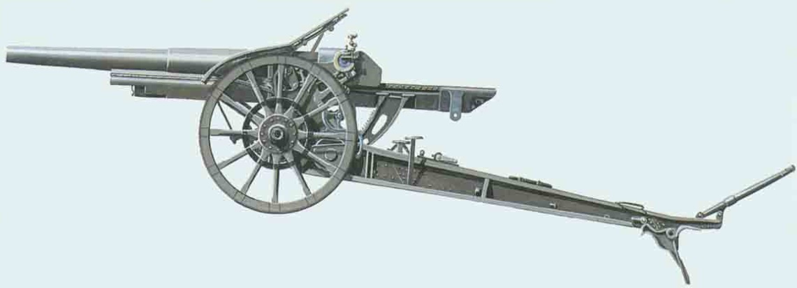
Carriage
The L13S was mounted on a box trail with side arms in the front half that allowed space for the gun to recoil at higher elevation angles. A shield was mounted on the front of the trail to protect the gun crew with a hinged opening to allow for forward observation of the gun sights. The rear of the trail was provided with a spade to stabilise the gun during firing which was supplemented by brake shoes acting on the rear of the wooden wheels which were fixed to the end of a steel axle passing through the trail.
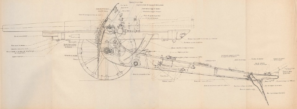
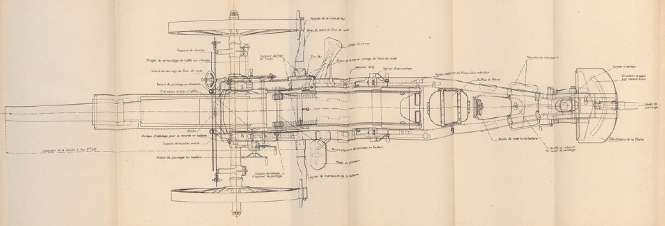 The L13S carriage was very similar in overall concept to that of the Mle 1897 with the gun pivoting on trunnions running in bearings at the top of the front of the trail. As with the Mle 1897, gun traverse was provided by moving the trail sideways by up to 3 deg either side along the wheel axle. A traverse hand wheel was provided on both sides of the trail for this purpose which rotated a traversing screw via an intermediary gear which then moved the trail along the wheel axle which was fitted with teeth for this purpose.

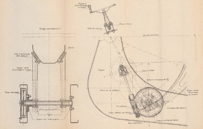
The gun was elevated by means of a pair of large toothed arcs fitted either side under the gun cradle. An elevating hand wheel was provided on the left-hand side of the carriage which rotated a pair of elevating arc pinions via a gear train to provide fine adjustment of the gun’s elevation.
The gun was transported by either 6 horse or via motorised tractor. When horse drawn, the gun was hooked up to a two wheel limber as shown and, to balance the gun between the two sets of wheel, it was locked in the full recoil position.
![]()
Gun Design
The L13S gun was 2.987 m or 28.4 calibres long and was of built-up construction as was normal during the early part of the 20th century. The gun consisted of a rifled tube with a chamber for the projectile at the rear behind which was an interrupted threaded section for the breech. A jacket was shrunk over the rear portion of the tube with fittings to support the single motion breech operated by a lever.
A interrupted screw breech was used with a single motion lever that, when operated, rotated the breech screw to unlock it before swinging it clear of the breech opening. At the same time an extractor ejected any spent cartridge. The centre of the breech was fitted with a striker that was struck by a large spring loaded hammer (marteau) to set off the shell cartridge. The hammer was cocked manually and released via a lanyard.

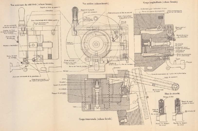
Recoil Mechanism
Unlike the German and British field howitzers used in WW1 which used hydro-spring recoil systems, the L13S used a much more sophisticated hydro-pneumatic recoil system. The L13S recoil system was contained within the cradle (berceau) on a recoil sled (traineau) on which the gun was attached which recoiled along runners either side of the cradle. The cradle extended some distance behind the breech to allow the gun to be fully supported for the full length of recoil.
Within the recoil sled, there were two cylinders in the lower part with the right-hand one forming the hydraulic buffer (frein) and the left-hand one forming the recuperator (recuperateur). At the front above these cylinders were 3 reservoirs. The hydraulic buffer is shown in the upper cutaway drawing below. The hydraulic cylinder was filled with oil (shown in blue) and contained a piston on the end of a tube attached to the front of the cradle so that, as the gun recoiled, the cylinder moved backwards while the piston stayed still. The piston contained small ports to restrict the flow of oil past it during recoil and, in so doing, absorbed most of the recoil energy helped a little by the air pressure in the recuperator.
The hollow piston tube (tige de frein) was also filled with oil and contained another piston on the end of a rod (contretigre) attached to the rear of the recoil sled. The purpose of this inner hydraulic buffer was to absorb the energy generated by the recuperator in order to bring the gun to a gentle stop when it was returned to battery. The hydraulic buffer oil level was topped up by oil from the small (petit) reservoir in the front of the sled.

The recuperator is shown in the lower cutaway drawing above and was responsible for returning the gun to battery after the recoil ended. The recuperator consisted of a cylinder in the lower part of the recoil sled, which recoiled with the gun, and a piston on the end of a rod fixed to the front of the cradle. As the cylinder moved backwards, the oil in front of the piston was forced into the two large (grand) reservoirs at the front of the recoil sled thus compressing the air inside. Once the recoil had stopped, this increased air pressure then forced the gun forward back into battery. The ambient air pressure was maintained at 500 psi.
Unlike the equivalent British Ordnance QF 4.5-Inch Howitzer, the L13S did not have to use a cut-off gear to restrict the length of recoil as the gun was elevated as there was always sufficient clearance for the recoiling breech above the ground. The maximum recoil distance of the gun was 1.25 m.
Sighting
The sights were mounted on a bracket fixed to the end of the left-hand gun trunnion and therefore elevation with the gun. As for nearly all howitzers, the sights were reciprocating to allow them to compensate for the carriage wheels not being level, which was the norm. Ignoring the spin drift of the shells, their trajectory normally lies in the vertical plane through the gun barrel. However, if the wheels and therefore the gun trunnions are not horizontal, this trajectory plane will be rotated away from the centre line of the gun cradle in the direction of the lowest wheel resulting in a large sighting error. To eliminate this effect, the sights were mounted on a reciprocating bracket that could be tilted sideways about an axis parallel to the gun to put the sights back into the same vertical plane as the projectiles. This tilting was performed using the knurled knob (bouton molete) and the cross-level bubble (niveau d’inclinaison) at the rear of the sight.
The required tangent elevation was set on the sight using the large knurled knob at the rear of the sight assembly which controlled the height of a toothed arc on which the sights were mounted- when raised, this tipped the sights forward with a tangent elevation scale provided marked in milliemes (the same as a NATO MIL with 6400 to 360 degrees). A clinometer was provided above the elevation adjustment knob consisting of a level bubble (niveau de tir) and a pair of knobs to set the angle of sight from -500 to -500 milliemes . To set the gun to the required quadrant elevation to hit a target at a particular range, the angle of sight and the tangent elevation was set on the sight and then the gun was elevated until the clinometer bubble was level.

The L13S was mainly used for indirect fire where the target was not visible in the sight. A dial sight (goniometre panoramique) was used to set the target direction for the gun in this mode which was basically a copy of the German Goertz sight invented in 1906. This consisted of a panoramic telescope with fixed eye piece and a sighting head that could be rotated up to 360 degrees. In use, one or more aiming points was set up for the gun which could take the form of a prominent feature in the landscape clearly identifiable on a map. The gun plotter then worked out the difference in bearing between a particular gun aiming point and the target which was then set up on the sight using the bearing scale and micrometer adjustment knobs. By aligning the sight on the aiming point, which could be in front of or behind the gun, this ensured that the gun was aligned with the target bearing.
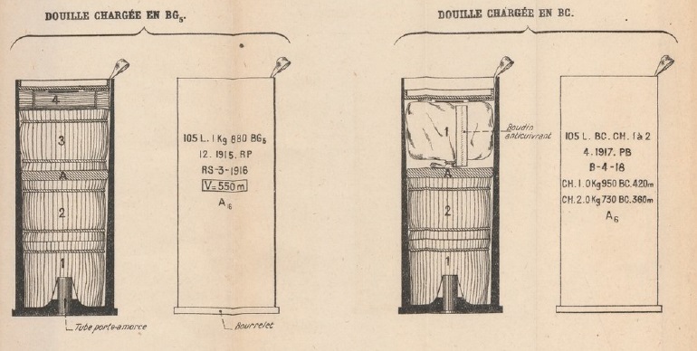
Ammunition
The L13S was a quick fire (QF) gun in British parlance which meant that it not only incorporated an effective recoil system but also used brass cartridges, both of which increased the rate of fire. Three separate charges were used numbered 0, 1 & 2 with 0 being the strongest. Charge 0 used four propellant bundles, Charge 1 used three and Charge 2 used two. With Charge 0, the muzzle velocity produced was 550 m/s; with Charge 1 it was 420 m/s; and with Charge 2 it was 360 m/s.
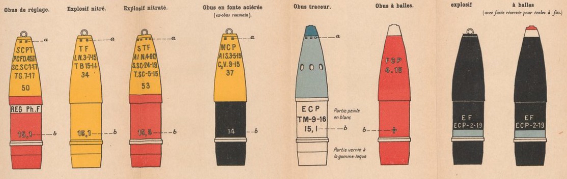
The L13S fired shells nominally weighing 15.7 kg and was used to deliver high explosive, Shrapnel and smoke.
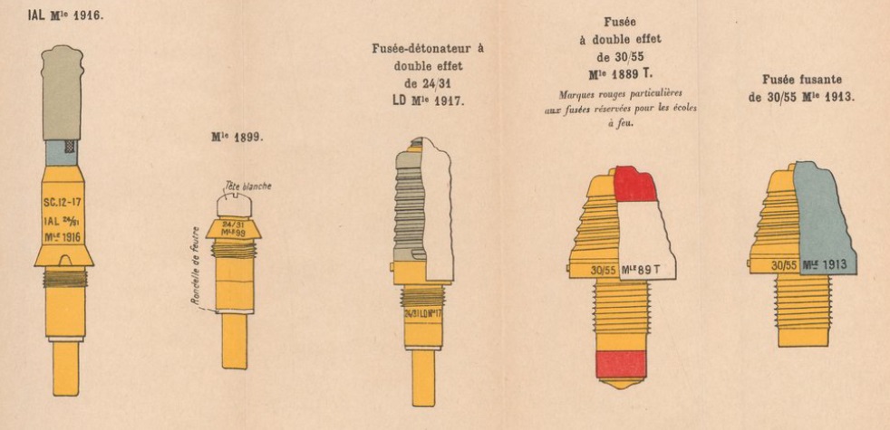
A range of fuzes were used with the shells for the L13S as shown below. The IAL Mle 1916 was an instantaneous percussion fuze which detonated the shell as it hit the ground. The Mle 1899 was a basic percussion fuze. The LD Mle 1917 (Longue Distance) was a time and percussion fuze that gave a 0-51 s time delay and was developed for long range artillery use. It was basically a longer version of the earlier ‘Beehive’ fuze. The Mle 1889 T was a time and percussion fuze providing a delay of 0-49 s. The Mle 1913 was a modified version used in the anti-aircraft role with the percussion function removed so that unexploded shells did not detonate on hitting the ground.
Canon de 105 L Mle 1913 Specifications
- Length: 6.3 m
- Maximum Width: 2.03 m
- Wheels: Wooden 1.33 m in diameter
- Weight of Gun & Carriage: 2300 kg
- Length of Gun: 2.987 m or 28.4 calibres
- Bore: 10.5 cm
- Muzzle Velocity: 550 m/s
- Maximum Range: 12,000 m
- Trail: Box trail
- Recoil System: Hydro-pneumatic
- Maximum Recoil: 1.25 m
- Rifling: Uniform 1 turn in 25 calibres
- Length of Rifling: 2.352 mm or 22.4 calibres
- Twist: Right-hand
- Grooves: 40
- Firing Method: Percussion
- Elevation: -5° to +37°
- Traverse: -3° left to +3° right
![]()