

During the Boer War (1899-1902), the British artillery were outclassed by the more modern weapons used by the Boers and, in particular, were out-ranged early on by the 155 mm Creusot BL guns called a ‘Long Tom’ by the British. The British answer was to convert a number of naval 4.7-inch guns for field use.
After the Boer War, heavy batteries of the Royal Garrison Artillery (RGA) were equipped with a so called quick-firing 4.7 inch gun but it was felt that a more effective field gun should be developed. As a result the Heavy Battery Committee was established in 1902, presided over by Colonel Perrott who had commanded the Siege Train in South Africa, to draw up the specification for the new heavy field gun. Suitable designs were invited from industry and trials were carried out on the most promising examples. After the trials, the Armstrong gun was accepted but none of the carriages was deemed satisfactory. New designs were therefore sought to produce a more practical carriage design taking into account the problems of moving such a heavy weapon around a modern battlefield. New trials were then carried out in 1904 using both horse and mechanised towing and, after further refinements, the design was accepted in 1905.
The new gun was designated the 60-Pdr BL Gun and was of 5 inch calibre. Although it was fitted with a recoil system that allowed consecutive rounds to be fired without the need for resetting the sights, it was designated a breech-loader (BL) rather than a quick-firer (QF). The reason for this is that it used bagged rather than metal cartridges that required the breech to be swabbed out after each round was fired thus slowing the rate of fire that could be achieved.
The 60-pdr served throughout WW1 and continued in service into the early part of WW2 until replaced by the BL 5.5-Inch Howitzer.
Mk I Gun
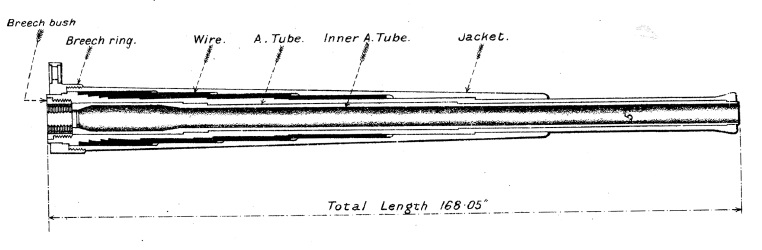
The Mk I gun consisted of an A-tube with an inner A-tube extending from the breech to the muzzle. Over part of the A-tube was wound successive layers of steel wire. The jacket was then fitted over the A-tube and steel wire and extended about two thirds of the length of the gun. It included longitudinal ribs on either side that ran in slots in the gun cradle to allow the gun to recoil. The Mk I* and I** guns differed from the Mk I in not having the inner A-tube and were introduced in 1915 to simplify manufacturing during WW1.
The breech was designed so that one pull on the lever unlocked the breech screw and swung it out of the way to allow the next round to be loaded. The breech made use of an interrupted screw that was rotated to lock and unlock the breech. Unlike quick-firing guns that used a brass cartridge case to provide obturation or sealing of the breech, this so-called breech-loading (BL) gun relied on the use of a mushroom shaped T-vent with an obturator pad on it to provide the necessary sealing against the rear of the breech chamber. The gun was fired using a friction T-tube down the centre of the T-vent operated by a lanyard.

Mk I Carriage
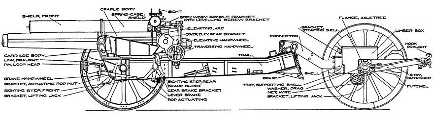
The Mk I carriage was designed to provide 21.5 degrees of elevation for the gun and 5 degrees of depression. It used a box trail with a spade at the rear to provide stability for the gun when firing.
The gun was mounted in a cradle in which it recoiled back and forth with the cradle fitted with trunnions to allow the gun to pivot on the carriage body. On the left-hand side of the carriage body was an elevating arc for the gun whose lower end engaged with the elevating mechanism operating by a hand wheel.
The carriage body was pivoted at the front on a saddle mounted on the carriage. A traversing mechanism was fitted to the saddle on the left-hand side to allow the carriage body and gun to be traversed by up to 4 degrees to either the left or right by means of a hand wheel. The Mk I carriage was designed so that the saddle could be hauled backwards on the trail so that the load could be distributed evenly between the gun and limber wheels during transportation.
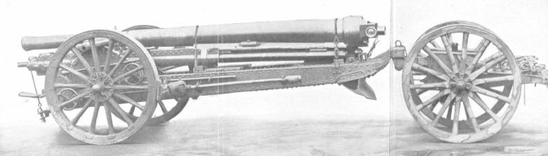
The Mk I carriage was fitted with wooden spoked wheels that were 5 foot in diameter. The wheels were fitted with brake shoes at the rear that were operated by two separate hand wheels at the front of the carriage.

The gun carriage was hooked up to a limber for travelling by using a rigid connector arm on the back of the trail that engaged with a pintle on the limber. The limber was then pulled by at least 8 horses depending on the conditions.
Recoil Mechanism
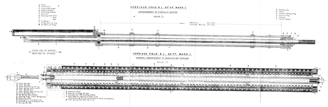
The hydro-spring recoil system was mounted above the gun and consisted of a hydraulic buffer between two spring recuperator cylinders. These were all attached to the gun cradle via two cradle collars. The hydraulic buffer piston rod was attached to a lug above the breech. When the gun recoiled, hydraulic oil was forced to flow through a port in the piston creating the resistance necessary to absorb the gun’s recoil.
The recuperators consisted of an inner rod connected to a lug above the gun’s breech and an inner and outer spring case. When the gun recoiled, a flange at the front end of the rod compressed the inner spring which, in turn, pushed the inner spring cylinder backwards. A flange at the front end of the inner spring case then compressed the outer spring. Therefore, as the gun recoiled, both the inner spring case and the central rod telescoped out of the back of the outer spring case compressing all the run-out springs at the same time.
Once the recoil of the gun was brought to a end, the run-out springs then returned the gun to battery. The front of the hydraulic cylinder piston rod formed a plunger that entered the control cylinder towards the end of run-out and displaced the hydraulic oil into the oil reservoir above it via a small passageway. The resistance created then brought the gun’s run-out to a controlled end.
Gun Sights
The gun was originally fitted with tangent sights on the right-hand side of the gun fixed to the front and rear cradle collars. The rear sight was fitted with a toothed rack to provide an elevation adjustment with a range scale graduated on it from 200-10,400 yds in units of 100 yds and a degree scale graduated from 0-20 degrees in units of 10 minutes. The sight also provided a deflection adjustment of 2 degrees left or right in units of 5 minutes.
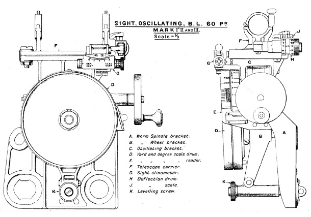
However, before WW1, the guns were fitted with oscillating sights mounted on a triangular bracket on the left side of the rear cradle collar. The purpose of the oscillating or reciprocating sight was to compensate for the effect of the gun’s wheels not being level (the normal situation) that had the effect of rotating the vertical plane defining the shell’s trajectory in the direction of the lower wheel. To correct for this, the sight mounting bracket was fitted with an oscillating bracket mounting the sights that could be tilted sideways to align it with the vertical plane using the levelling screw. Since the oscillating bracket rotation axis was parallel to that of the gun’s axis, this ensured the sights were in the same vertical plane as the trajectory of the shell.
For direct fire, a No. 5 sighting telescope and a clinometer was fitted on a sight carrier that could be rotated in elevation on the oscillating bracket using the hand wheel provided. A yard and degree graduated scale drum was provided. The sight carrier was also fitted with a deflection adjustment with degree scale that was used to compensate for the rightwards spin drift of the projectiles.
For indirect fire, a No. 7 dial sight was fitted to a carrier mounted on the sight bracket. In indirect fire, the required elevation and azimuth bearing were provided to the gun detachment by a plotting officer. The required elevation was set using the sight elevating hand wheel to dial in the required elevation angle and then the gun was elevated until the clinometer bubble was levelled. The required target bearing was defined as an offset bearing from the gun’s aiming point that was normally in the direction of a known feature on the landscape but could be in the direction of aiming posts set up for this purpose – these could be in front of the gun or behind it. The required offset bearing was then set up on the dial sight that rotated the upper sighting head by this angle while leaving the viewing eye piece fixed. The gun was then traversed until the aiming point was centred in the dial sight which then meant that the gun was aligned with the target bearing.
Mk I gun on Mk II Carriage
To simplify manufacturing during WW1, the facility to haul the gun and saddle backwards on the trail to even up the weight distribution between the carriage and limber wheels was dispensed with. However, since this put a lot more weight on to the front wheels, these had to be changed to steel traction engine wheels. In addition, the extra weight of the Mk II carriage then required it to be pulled by a holt tractor rather than horses.

However, in 1916, General Haig, the British Commander-in-Chief, requested a change to a lighter carriage. Rather than returning to the Mk I carriage with a moveable saddle, the guns recoil mechanism was modified to allow the gun to be withdrawn backwards to its fully recoiled position and then locked to the trail. With this change, a return was made back to lighter wooden spoked wheels.
Mk I Gun Ammunition
The cartridges used by the BL 60-Pdr were made up of cloth bags containing Cordite with an igniter at each end formed using RFG gunpowder as shown below.
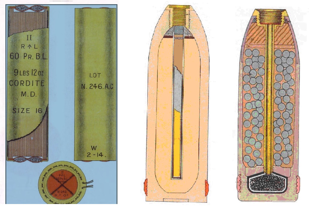
Two main types of shell were fired: high-explosive (HE) and shrapnel. The HE shells were filled with Lyddite, TNT or Amatol and were detonated using a variety of direct action and percussion fuzes; for example, the No. 101 percussion fuze.
The shrapnel shells contained between 900-1000 lead/antimony balls. They were detonated using a variety of time and percussion fuzes including the No. 83. The time fuze could be set to provide a time delay of up to 22 time units before setting off a powder charge in its base. The flash from this charge then travelled down a central tube in the shell to ignite a gunpowder bursting charge in the base separated from the shrapnel balls by a steel disk. When the bursting charge was ignited, it blew off the fuze from the front of the shell and propelled the shrapnel balls at high speed to spray the ground in front of the shell.
The original shells had a 2 calibre radius head (CRH) giving them a range of 10,300 yds at maximum elevation but, in 1917, a more streamline 8 CRH shell design was introduced extending the maximum range to 12,300 yds.
Mk II gun on Mk IV Carriage
Mk II Gun
The Mk II gun was introduced in 1918 and was 5-calibres longer than the Mk I increasing the maximum range from 12,300 to 15,700 yds. The main change compared with the Mk I gun was to a hydro-pneumatic recoil system mounted under the gun.
Its construction was similar to the Mk I* being fitted with a rifled A-tube with steel wire wound over part of its length and with a jacket shrunk down on top extending over two thirds of the length from the breech. The breech ring fitted over the end of the A-tube and screwed into the jacket. The jacket was fitted with longitudinal projections on either side that slid in grooves in the gun cradle during recoil. The Mk II* gun was similar to the Mk II but included an inner A-tube.
A new breech design was used with a Welin breech screw and Asbury single motion mechanism. The main change compared with the breech in the Mk I gun was the use of percussion rather than friction tube firing of the cartridges – this required a ‘Tube, Percussion, S.A. Cartridge’ to be inserted into the back of the breech before firing. The mechanism was triggered using a lanyard pulled from the right-hand side of the gun.

Mk IV Carriage
The Mk IV carriage also used a box trail but was designed to give the Mk II gun a greater firing range with the maximum elevation increased to 35 degrees. A saddle was used to support the gun cradle that pivoted at the front on the trail to provide traversing of the gun by up to 4 degrees to the left or right controlled via a traversing gear and hand wheel. The gun was elevated by an arc under the centre line of the gun to provide maximum rigidity and was controlled via a hand wheel.
For towing, the rear of the trail was fitted with an eye that fitted on to a pintle on the front of the limber. Before it could be transported, the gun and recoil cylinder block were hauled backwards using ropes and tackles to even out the weight distribution between the carriage and limber wheels. This was made possible by first unbolting the hydraulic and recuperator piston rods from the front of the cradle. Either horse or mechanised towing could be used.
In the 1920’s, the wooden wheels were provided with solid rubber tyres (Ml IVR carriage) but, in the 1930’s, these were replaced with metal wheels mounting pneumatic tyres (Mk IVP carriage) to facilitate high speed towing.
The recoil mechanism was of the hydro-pneumatic type and consisted of a cylinder block that recoiled in the cradle along with the gun. The cylinder block consisted of three cylinders bored longitudinally. The right-hand cylinder was the hydraulic buffer with a piston connected to a rod bolted to the front of the cradle. As the gun recoiled, oil was forced past openings in the piston creating the resistance necessary to absorb the recoil energy. The passage of oil though the piston was controlled by three openings in it opposite to a corresponding number of ports in the recoil valve fixed to the piston rod in front of the piston. At the start of the recoil, the ports and openings were aligned and allowed maximum oil flow through through the piston. However, the piston was keyed into two spiral grooves on the inside surface of the hydraulic cylinder that rotated it on the piston rod as the gun recoiled. After a set length, the recoil valve closed off the flow of oil thus bringing the recoil to an end. The gun was fitted with a so-called cut-off gear that was designed to shorten the length of recoil of the gun as it was elevated to stop it hitting the ground or cradle during recoil. The mechanism used resulted in the hydraulic cylinder piston rod and recoil valve being rotated by the required amount for a given gun elevation to produce the required length of recoil. The resulting recoil length was 54 inches at 0 degrees elevation reducing to 24 inches at 35 degrees elevation.
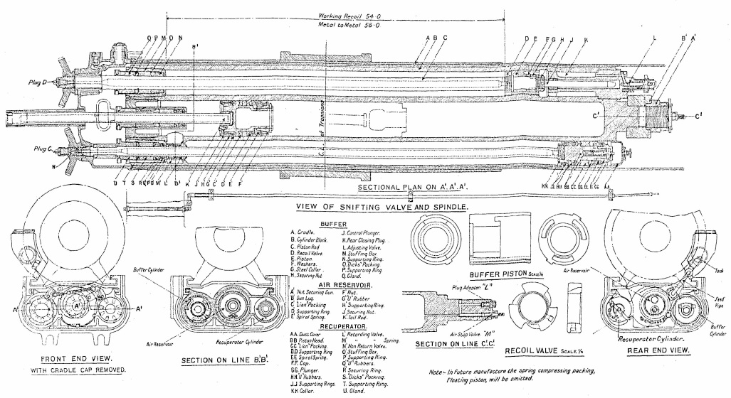
The left-hand cylinder in the recoil mechanism was the recuperator and contained a piston on the end of a rod fixed to the front cap on the cradle. As the gun recoils, the oil in front of the piston was forced into the front of the centre cylinder forming an air reservoir where it was separated from the compressed air at the other end by a floating piston. This flow of oil also helps to absorb the energy of recoil. As the gun recoiled and oil flowed into the air reservoir, the floating piston was forced backwards compressing the air in the air reservoir. At the end of recoil, this compressed air then forced the floating piston forward which, in turn, forced the oil back into the recuperator. This then forced the recoil cylinder block forward running out the gun. The final movement of the recoil mechanism was controlled by the control rod on the end of the hydraulic piston rod that had to displace the oil in the control chamber damping out the final forward movement of the gun..
Mk II Sights
The Mk I gun sights were changed to calibrating sights on the Mk II gun using a No. 9 carrier for the No. 7 dial sight. This allowed the sight to set the muzzle velocity and to indicate the gun’s range as a function of elevation angle.
The sight assembly was mounted on a supporting bracket that was pivoted on the left-hand gun trunnion with the front end engaged with a projection on the cradle to ensure that it elevated with the gun. The sight was oscillating or reciprocating in a similar way to the sights on the Mk I gun to correct for any tilting of the carriage wheels. The necessary tilting of the sights was provided by the elevating arc bracket that incorporated a cross-level for alignment purposes.
The socket bracket for the No. 7 dial sight was fixed to the top of a toothed elevating arc that was raised by a worm gear controlled by the hand wheel provided. A separate bracket was bolted to the sight socket bracket to mount the sight clinometer. A variety of range scales could be attached to the elevating arc depending on the ammunition being used. The range was read from the scale using a reader bar that pivoted at the rear and was adjusted at the front using a key to provide corrections of up to 150 fps for the ammunition being used. Therefore, to set the required elevation or range for the gun, the muzzle velocity correction was applied and the sight was then elevated to give the required elevation angle or range on the scale. The gun itself was then elevated until the clinometer was levelled.
To compensate for the spin drift of the projectiles, the sight carrier is set at a fixed angle of 2 degrees 20 minutes to the left.

Mk II Gun Ammunition
The shells used in the Mk II were similar to that of the Mk I with the addition of a gas shell. This was basically similar to the HE shell but used a sealed container behind the percussion fuze for the bursting charge. The shell was filled via a charging hole drilled in the shell casing and sealed with a steel plug. The Mk II gun fired the more streamlined 8 CRH shells.
60-Pdr BL Mk I Gun and Mk I Carriage Specifications
- Length: 21 ft 7 inch
- Maximum Width: 6 ft 6.5 inch
- Wheels: 5 ft diameter
- Weight of Gun & Carriage: 88 cwt 1 lb
- Length of Gun Barrel: 14 ft
- Length of Bore: 13 ft 4 inch
- Bore: 5 in (127 mm)
- Weight of Gun & Breech: 39 cwt
- Muzzle Velocity: 2030 fps
- Maximum Range: 12,300 yd (8 RCH) shells
- Trail: Box
- Recoil System: hydro-spring
- Maximum Recoil: 54 inch
- Rifling: Polygroove with modified plain section
- Length of Rifling: 11 ft 4 inch
- Twist: Right-hand twist with 1 turn in 30 calibres
- Grooves: 24
- Firing Method: Friction T-tube
- Elevation: -5° to +21.5°
- Traverse: -4° left to +4° right
60-Pdr BL Mk II Gun and Mk IV Carriage Specifications
- Length: 24 ft 10.5 inch
- Maximum Width: 8 ft
- Wheels: 5 ft diameter
- Weight of Gun & Breech: 43 cwt 38 lb
- Weight of Gun & Carriage: 110 cwt 14 lb
- Length of Gun Barrel: 16 ft
- Length of Bore: 15 ft 5 inch
- Bore: 5 in (127 mm)
- Firing Mechanism: Percussion
- Muzzle Velocity: 2,145 fps
- Maximum Range: 15,700 yd
- Trail: Box
- Recoil System: hydro-pneumatic
- Maximum Recoil: 54 inch
- Rifling: Polygroove with modified plain section
- Length of Rifling: 13 ft 5 inch
- Twist: Uniform right-hand twist with 1 turn in 30 calibres
- Grooves: 32
- Firing Method: Percussion
- Elevation: -5° to +35°
- Traverse: -4° left to +4° right
![]()