

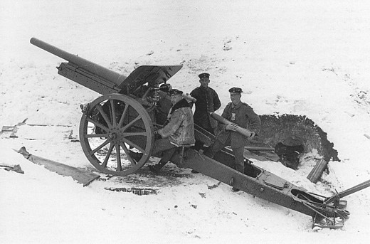
In 1904, the 10 cm Kanone 04 (K04) was introduced into service to provide a mobile artillery piece capable of firing high explosive shells to a much greater range than the equivalent howitzer then in service, the somewhat obsolete 10.5 cm leichte Feldhaubitze 98. However, by 1911, with a future threat from aviation technology identified, the APK ( Artillerie Prüfungs Kommission or artillery testing commission) specified the requirements for a new 10 cm field gun with dual use: as a long range artillery piece and as an anti-aircraft gun. Designs were produced by both Rheinmetall and Krupp but, after considerable testing and modification, a Krupp design was eventually adopted and introduced into service starting in 1915 as the 10 cm Kanone 14 (K14).
To provide the anti-aircraft function, the K14 used a complicated 2-man laying system and was also equipped with a circular steel mounting platform to allow faster traversing of the gun. In contrast with the 30 deg maximum elevation of the K04, the K14 maximum elevation was increased to 45 deg to make it more useable for anti-aircraft use. However, possibly because the difficulty of firing at a moving aeroplane was not fully appreciated when the gun was designed, it proved the be a failure as an anti-aircraft gun. A few years later, a simplified version of the gun was produced by Krupp as the 10 cm Kanone 17 with the 2-man laying system abandoned.
Carriage
The K14 used a box trail fitted with side arms to provide space for the gun to recoil downwards. It was fitted with a splinter shield and a spade and a deployable traversing pole at the rear . The carriage was mounted on wooden wheels with steel tyres. Brake pads were provided in front of the wheels to help stabilise the gun during firing operated by a lever on the right side just above the wheel axle. A seat was provided for the gun layer on the left of the carriage. The gun was light enough to be towed as a single load by a team of six horses.
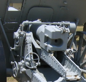
The gun was mounted on a cradle containing the hydro-spring recoil system and was fitted with rear mounted trunnions to minimise the change in height of the breech as the gun was elevated. The cradle trunnions were supported in bearings at the top of the saddle on either side which had triangular side walls. The saddle pivoted in the horizontal plane on a bearing at the front of the trail allowing the gun to be traversed by up to 3 degs either side via a screw jack on the left-hand side of the trail operated by a hand wheel. The gun was elevated via a horizontal pinion shaft and two elevating arcs under the cradle behind the shield. To support the unbalanced weight of the gun and cradle, a spring equilibrator was mounted under the cradle between the two elevating arcs.
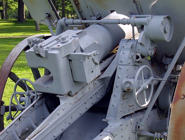
The K14 used 2-man laying with the gun layer sitting on the left responsible for sighting the gun on to the target and the right-hand crew member responsible for setting the range of the gun. The gun layer operated the two hand wheels on his side of the cradle to traverse the gun and to elevate the gun in order to align the sights with the aiming point, whether in the air or on land. The gun layer effectively set the angle of sight on the gun; that is, the angle of the target above the horizontal plane through the gun. The right-hand crew member was provided with a separate hand wheel on the right-hand side of the cradle which he used to elevate the gun to give the required range on the range drum provided just above the right-hand trunnion. The range drum indicated the range in metres and the tangent elevation angle in degs.
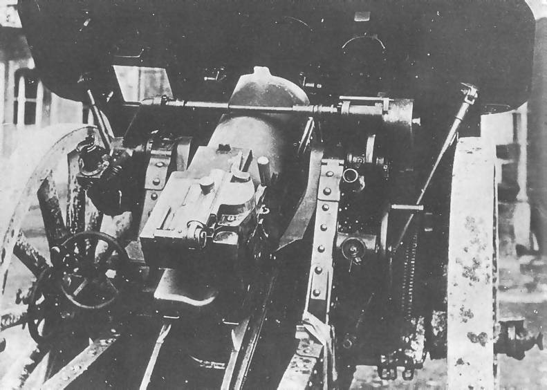
The way the sight operated is described separately below. The elevation of the gun was mechanically complex using a planetary gearbox that can just be seen in front of the right-hand elevating hand wheel. Inside the gearbox, the central sun gear was connected to the end of a shaft that ran through the hollow elevating pinion shaft to a worm wheel and gearbox on the opposite side of the trail. The worm wheel was rotated via a worm on the end of a shaft connected to the gun layer’s elevating hand wheel. Inside the planetary gearbox, the sun gear meshed with three planetary gears on a carrier fixed to the elevating pinion shaft with the planetary gears also meshing with the outer ring gear. When the gun layer’s elevating hand wheel was turned, this effectively rotated the planetary gear carrier which, in turn, rotated the elevating arc pinions thus elevating the gun to give the required angle of sight.
As well as forming part of the planetary gear cluster, the ring gear was also fitted with gear teeth on the outside that meshed with a worm fitted to the end of a shaft connected to the right-hand elevating hand wheel. When the loader rotated this hand wheel, it had no effect on the position of the sun gear, and therefore the sights, but it did rotate the planetary gear carrier and therefore altered the tangent elevation of the gun. With this complicated mechanical arrangement, the gun could therefore be independently elevated to adjust the angle of sight and the range to the target.
The range drum mounted on the right-hand gun trunnion indicated the tangent elevation of the gun. It was connected via a drive shaft (missing from above picture) to the planetary gear box and was turned by the movement of the ring gear.
Gun Design
The gun was 3.68 m or 35 calibres long with the rifled part of the barrel being 27 calibres or 2.84 m in length. The gun was of built up construction with a 2-section jacket shrunk on to the rifled tube and extending for about two thirds of the length of the barrel. Brackets were provided on the jacket sections to support guides that allowed the gun to recoil along the top of the cradle
The jacket was shaped at the rear to support a horizontal sliding breech block of Krupp design that opened to the right. The breech could be opened manually by using the operating handle on the right of the breech. However, in order to provide a high rate of fire against aeroplanes, the breech operation was semi-automatic using the mechanism mounted on top of the breech. After firing, as the gun returned slowly back to battery, it is likely that a plunger underneath the breech was operated as it came into contact with the cradle. The plunger rotated the breech operating spindle thus opening the breech and ejecting the empty cartridge case. At the same time, a rack and pinion at the top end of spindle compressed a strong spring inside the mechanism on the top of the breech. When a new cartridge was inserted into the breech depressing the extractor, this automatically triggered the mechanism to close the breech. The breech incorporated an axial striker to fire a loaded cartridge which was fired using a lanyard fitted to the trigger arm on the right-hand side of the breech.
Recoil System
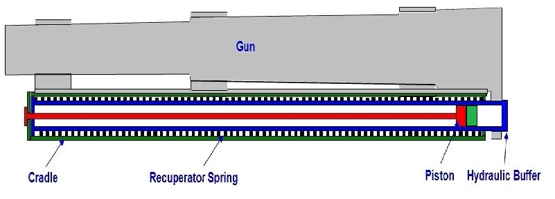
The K14 used a hydro-spring recoil system mounted within the cradle. This consisted of a oil filled hydraulic buffer whose cylinder was connected to a lug under the breech with a coaxial spring mounted on the cylinder to form the recuperator. The hydraulic piston was fixed to the end of a rod attached to the front of the cradle.
As the gun recoiled and the hydraulic cylinder was pulled backwards, the oil was forced to flow through the piston resisting its movement and absorbing the energy of recoil. The piston was fitted with ports for this purpose but was also fitted with a rotating valve with a similar set of ports. The rotating valve was keyed into a pair of spiral grooves in the surface of the hydraulic cylinder that caused it to rotate when the gun recoiled. At the start of recoil, both sets of ports were aligned to provide maximum oil flow rate but, as the gun recoiled and the rotating valve rotated, a point was reached where the sets of ports were no longer aligned and the flow of oil was stopped bringing the recoil to an end. At the same time that the hydraulic cylinder recoiled backwards, it compressed the large coaxial spring so that, once the recoil had been brought to an end, the spring forced the gun back into battery.
Even using rear mounted gun trunnions that limited the height movement of the breech, the recoil length had to be shortened as the gun was elevated in order to stop the breech hitting the ground. The K14 therefore used a variable recoil mechanism. The length of recoil was varied by rotating the piston rod as a function of the gun’s elevation angle to change the cut off point for oil passing through the piston and rotating valve. In the K14, the front end of the piston rod was fitted with a pinion that engaged with a toothed arm on the end of a control rod mounted inside the cradle. The control rod was rotated by a mechanism near the left gun trunnion as the gun was elevated which in turn rotated the piston rod and shortened the length of recoil. The recoil length varied between 1.55 m to 0.95 m at max elevation.
Sights
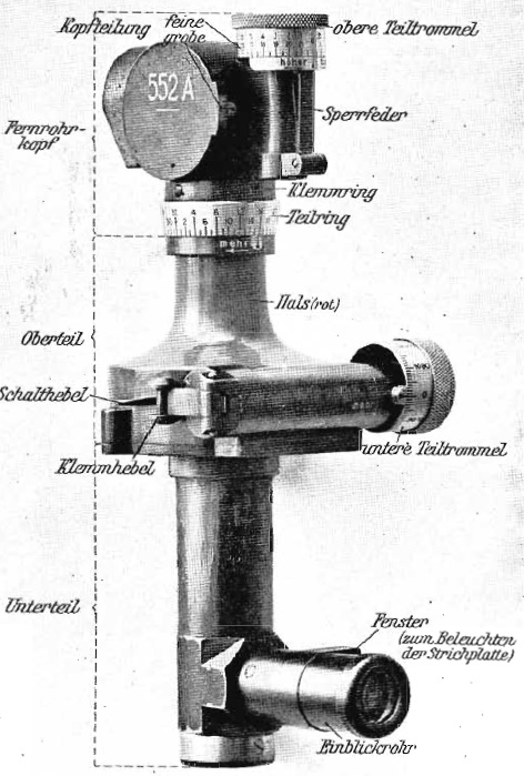
The basic sighting device used on the K14 was a dial sight or panoramic telescope (Rundblickfernrohr) that was invented by Goertz in 1906. The sights were reciprocating to allow them to compensate for the wheels and, therefore, the trunnions not being level which was the norm. If uncorrected, this would lead to the sights not being in the same vertical plane as the gun barrel since this would be rotated away from the centre line of the carriage in the direction of the lowest wheel leading to a large sighting error especially at higher elevation angles.
The sight assembly was attached to a sight gearbox bolted to the left-hand trunnion. The tilt in the gun trunnions was overcome by mounting the sights on a reciprocating bracket that was able to tilt sideways on the sight gearbox. In practice, the reciprocating bracket was tilted sideways using the butterfly knob provided until the cross-bubble on the dial sight bracket was levelled putting the sights back into the same vertical plane as the gun barrel.
As with most other German field guns of this period, the dial sight was mounted on the end of a toothed sight arc – when raised, this tilted the sight forward in the elevation plane by the required elevation angle. In the way in which the 2-man laying worked on the K14, it was necessary to automatically apply the tangent elevation set by the right-hand crew member to the sight arc so that the line of sight remained unchanged. This was achieved via the drive rod connected to the range drum that ran across the top of the gun down to the sight gearbox that rotated a pinion that messed with the sight arm teeth.
When used in indirect fire mode, the required target bearing was specified relative to an aiming point set up for the gun that could be seen in the dial sight – this could be a prominent feature in the landscape or it could be sighting rods specially set up some distance from the gun. The Goertz sight had a fixed eyepiece but the sighting head at the top could be rotated through 360 deg using the micrometer knob provided. A graduated ring was provide to indicate the angle of rotation. The relative bearing for the target was set up on the dial sight and then the gun traversed until the aiming point was centred in the sight which meant the gun was then aligned with the target bearing.
In indirect fire mode, target range was specified and the right-hand crew member elevated the gun until this was indicated on the range drum. The gun layer would then have used his elevating hand wheel to change the elevation of the gun until the longitudinal bubble on the sight clinometer incorporated into the dial sight bracket was level.
Ammunition
The K14 fired fixed ammunition comprising of the shell with the brass cartridge case attached. The case included a primer in the base that was struck by a striker to fire the projectile.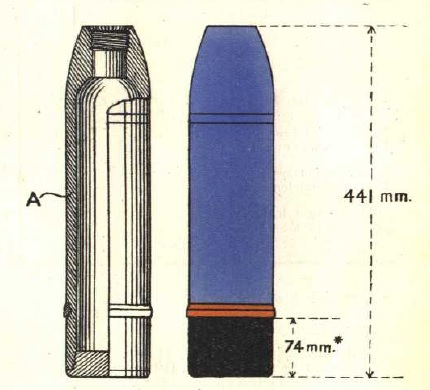
The K14 originally fired the 10 cm Gr. 96 round shown on the right that was 441 mm long or 4.2 calibres and used a 2.5 calibre radius head (CRH). It contained a relatively large bursting charge of 2.2 kg of TNT or Picric Acid. The nominal weight of the complete shell was 18 kg. It was fitted with a Gr. Z. 04 percussion fuze that also was fitted with an optional delay.
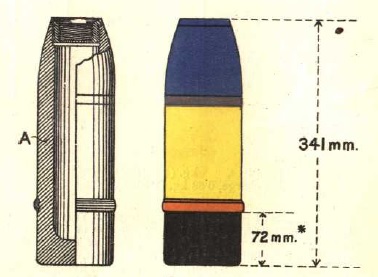
The K14 also fired the 10 cm Gr. Patr. round shown on the right. The was a much shorter shell than the 10 c G. 96 shell that used a much small bursting charge of 0.67 kg of Picric Acid but had thicker steel walls giving it a weight of 17.8 kg. It was fitted with a Dopp. Z. 92 time and percussion fuze and was basically an anti-personnel projectile.
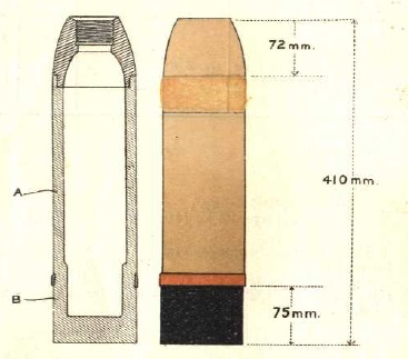 The 10 cm Gr. 15 shell was developed for the K14 at the start of WW1 which had a length of 410 mm and was filled with a bursting charge of 1.8 kg of Picric Acid. It had a nominal weight of 18 kg. It was fitted with a Gr. Z. 04 percussion fuze or a Dopp. Z. 15 triple action fuze. The latter could be used as a time fuze or a percussion fuze with or without a delay.
10 cm Kanone 14 Specifications
- Length: 6.72 m
- Maximum Width: 1.86 m
- Wheels: Wooden 1.53 m in diameter
- Weight of Gun & Carriage: 2820 kg
- Length of Gun: 3.68m or 35 calibres
- Bore: 10.52 cm
- Muzzle Velocity: 585 m/s
- Maximum Range: 11,050 m
- Trail: Box trail
- Recoil System: Hydro-spring
- Maximum Recoil: Variable 1.55 m to 0.95 m at max elevation
- Rifling: Polygroove with modified plain section
- Length of Rifling: 27 calibres (2.84 m)
- Twist: Progressive with 1 turn in 45 to 1 turn in 25 calibres
- Grooves: 32
- Firing Method: Percussion
- Elevation: -5° to +45°
- Traverse: -3° left to +3° right
![]()