

The Canon de 155 Mle 1917 GPF (Grande Puissance or great power Filloux) was designed during WW1 by Colonel Louis Filloux while working at the state arsenal at Puteaux (Atelier de Construction de Puteaux) in order to provide the French Army with a long range heavy field gun. It was used in the remainder of WW1 and up to WW2 and was also adopted by the United States as the 155 mm Gun Model 1917.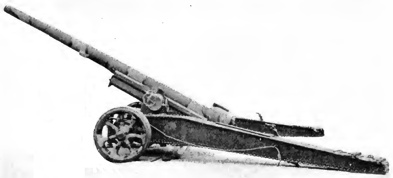
Carriage
The carriage was of split trail design with spades at the end of each leg to help steady the gun during firing. The trail legs pivoted on the side wings of the bottom carriage. The bottom carriage provided a transverse chamber at the front for the wheel axle that pivoted on a longitudinal pin to accommodate for uneven ground. In the original carriage, the axle was supported on leaf springs when being transported but was lowered on to the axle using jacks to put it into the firing position. The axle mounted wheels fitted with a pair of rubber tyres suitable for mechanised towing. The wheels could also be fitted with Cingoli which were articulated plates that increased the contact area of the wheels on the ground making it easier to support the weight of the gun on soft ground. The carriage was equipped with hand operated drum brakes on each wheel.
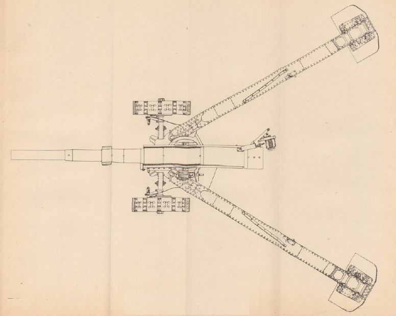
The gun recoiled on guides on either side of the cradle that consisted of a steel casting containing the recoil system. It was fitted with trunnions on either side for mounting on the top carriage to allow the gun to be elevated to 35°. The top carriage in turn was mounted on the bottom carriage on a horizontal bearing that allowed the gun to be traversed by up to 30° in either direction.

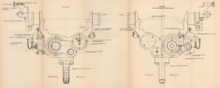
The top carriage shown below was provided with a hand wheel at the rear to traverse the gun that operated a worm gear at the bottom front via a gear train that engaged with a toothed arc on the lower carriage. The hand wheel on the left-hand side of the top carriage operated a large worm gear running fore-aft via a gear train that engaged with the elevating arc under the gun cradle.
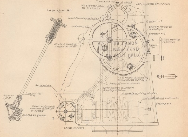
The worm gear and toothed arcs for both the traversing and elevating mechanism can be seen in the drawing below.

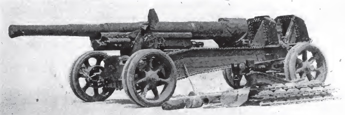
For mechanised towing, a limber with a pair of steerable wheels and a towing bar was fixed to the rear of the trail. In order to prepare for this, the gun was unbolted from the recoil mechanism and slid further back on the trail and then clamped in position to even the weight distribution between the two pairs of wheels. Both pairs of wheels were provided with sprung suspension to make towing at a higher speeds possible.
Gun Design
The gun was 5.91 m or 38 calibres in length and of built up construction. The jacket (manchon) was made up of four separate sections which were shrunk on to the rifled tube extending 3/4 of the way to the muzzle. The breech ring (frette du culasse) was screwed on to the rear of the jacket and included a lug underneath to attach the gun to the recoil system. The gun was fitted with rectangular bronze runners (fourrures) fixed to the jacket that allowed the gun to recoil within guides on either side of the cradle.

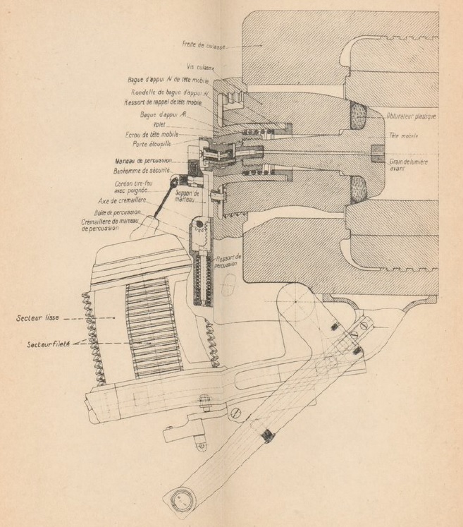
The GPF fired bagged cartridges and was fitted with an interrupted thread breech. A single motion operating lever was fitted and, when pulled back and to the right, rotated the breech plug to allow it to be withdrawn past the interrupted thread and then swung to the right hand side of the breech ring. In order to support the weight of the breech when it was opened and closed with the gun elevated, a spring strut was mounted on top of the breech ring that connected to the breech mechanism.
Obturation or sealing of the breech was accomplished by a mushroom shaped obturator (tete mobile) in the centre of the breech plug with a sealing ring behind its head (obturateur plastique). When the breech was closed, the sealing ring was pressed against the tapered end of the combustion chamber. When the round was fired, the combustion chamber pressure forced the obturator backwards inside the breech plug compressing the sealing ring and forcing it harder against the chamber sides to seal the breech. The bagged charges were igniting using a percussion cartridge inserted into the back of the breech whose flash travelled down a central vent in the breech plug. The hammer to fire the percussion cartridge via a firing pin was operated via a short lanyard at the back of the breech.
Recoil System
The GPF incorporated a hydro-pneumatic recoil system built into the cradle and consisted of 3 separate cylinders. The hydraulic buffer was on the left; the recuperator cylinder was on the right and the smaller diameter pneumatic cylinder was in the middle.
The hydraulic buffer consisted of an oil filled cylinder housing a piston on the end of a hollow rod (tige creuse du frein) that was bolted to the lug on the breech ring so that, when the gun was fired, the cylinder remained stationary and the piston was drawn backwards. Inside the hollow piston rod was an inner rod (contre tige) with grooves cut into its surface. The piston in turn was fitted with ports that allowed the oil to seep past it during recoil via the grooves in the inner rod providing enough constriction to absorb the energy of recoil.
As with many howitzers, it was necessary to restrict the length of recoil of the GPF as the gun elevated to prevent the breech hitting the ground. In the case of the GPF, this was accomplished by rotating the inner piston rod as the gun elevated which had the effect of reducing the contact area between the grooves and the piston ports increasing the braking effect. The mechanism for doing this can be seen in the drawing below at the bottom left. The mechanism was adjustable to give the order of about 1.8 m of recoil at 10° of elevation and about 1.1 m at 28°. Although the length of recoil was reduced as the gun was elevated, it was still necessary to dig a pit under the breech in order to provide enough clearance during recoil.
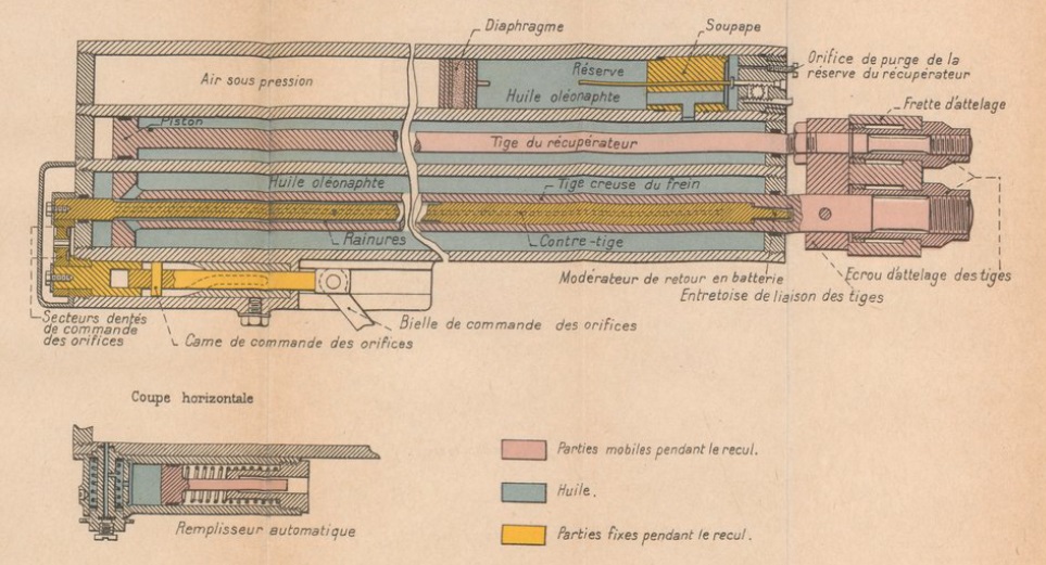
The recuperator was responsible for returning the gun to battery after the recoil had ended. The recuperator was made up of two cylinder. The hydraulic cylinder was filled with oil with a piston fitted on the end of a rod connected to the breech lug. As the gun recoiled, the piston forced the oil behind it into the pneumatic cylinder. Inside the pneumatic cylinder was a floating piston with air in front of it and oil behind. As the gun recoiled, the oil forced out of the hydraulic cylinder, pushed against the floating piston which, in turn, compressed the air in front of it. This absorbed some of the gun’s recoil energy but, once the recoil had been brought to an end, the air pressure in the pneumatic cylinder then forced the gun back into battery. The ambient air pressure in the pneumatic cylinder had to be maintained at about 600 psi.
Sights
Ignoring the effects of spin drift and the wind, the trajectory of shells will normally lie in the vertical plane through the gun. However, if the carriage wheels and therefore the gun trunnions are not level, this vertical plane will rotate in the direction of the lowest wheel and will no longer be aligned with the carriage centre line. If not corrected, this will lead to a large error in the sights especially at larger elevation angles.
In the GPF, the sight assembly shown below was mounted via its front and rear trunnions (tourillon) on a sight mounting bracket fixed to the left-hand gun trunnion. As the gun elevated, the sight trunnion axis remained parallel to the gun. At the front of the sight mounting bracket was an adjuster that allowed the sight assembly to be tilted about this axis and, by using the transverse spirit level (petit niveau), it was possible to restore the sights to the same vertical plane as the gun overcoming the problem of uneven carriage wheels.

The required quadrant elevation for the gun needed to hit a target at a particular range was set on the sight using the rear adjustment knob (tambour des minutes). The scale for the knob indicated minutes of angle while the drum (tambour des degres) on the side of the sight indicated degrees. When the knob was turned, it rotated a worm wheel which, in turn, rotated the internal sight arm on which the sights were mounted by the same angle. In practice, after the required quadrant elevation was set on the sight the gun was then elevated until the large spirit level (grand niveau) was level.
The GPF was mainly used for indirect fire where the target cannot be seen in the sights. In this mode of firing, the target direction is specified in terms of an offset bearing from an aiming point defined for the gun which could, for example, be a prominent feature on the landscape which could be in front of the gun, behind the gun or to one side. To aim the gun at the target required the offset bearing to be set on the sight and then the gun traversed until the aiming point was centred in the sight.
By the start of WW1, most nations had adopted a panoramic telescope sight based on the German Goertz design for indirect firing that provided a fixed eyepiece but with a sighting head that could be rotated 360 degrees in azimuth. In contrast, the GPF used a collimator as the sighting device. The required offset target bearing was set on the sight by depressing the collimator column in order to allow it to be rotated with its bearing scale marked from 0 – 40 in units of 100 decigrades with 4000 decigrades corresponding to 360 degrees. The upper drum (tambour gradue) then allowed fine adjustment in decigrades units from 0 – 100.
The main problem with the collimator sight was that the gunner sometimes had to clamber on to the gun to be able to see the aiming point in the sight which was not as quick or as convenient to use as a panoramic telescope sight with fixed eyepiece. In comparison, the corresponding US version of the GPF used an M4 panoramic telescope making the gun laying much quicker and much more convenient than on the GPF with a collimator sight.
Ammunition
The GPF used bagged cartridges with an igniter pad sown into the base which was ignited by the flash from the percussion cartridge at the back of the breech vent. Several different sized cartridges were used (0, 1 & 2) giving different muzzle velocities with Charge 0 being the most powerful.

The GPF fired shells nominally weighing 43 kg and were mainly high explosive filled. However, smoke and gas shells were also fired. The earlier shells were made of steel (acier) but the Mle 1915 and 1918 shells were made from cast iron (fonte acier) and, with a more streamlined shape, gave a great muzzle velocity and range.

A wide range of fuzes were used with the shells ranging from super quick percussion to dual effect time and percussion.

Canon de 155 Mle 1917 GPF Specifications
- Length: 8.5 m
- Maximum Width: 2.674 m
- Wheels: Metal with rubber tyres 1.16 m in diameter
- Weight of Gun & Carriage: 9009 kg
- Length of Gun: 5.91 m or 38 calibres
- Bore: 15.5 cm
- Muzzle Velocity: 735 m/s
- Maximum Range: 16,450 m
- Trail: Split box trail
- Recoil System: Hydro-pneumatic
- Maximum Recoil: 1.8 m at 10° elevation and 1.1 m at 28°
- Rifling: Uniform 1 turn in 29.9 calibres
- Length of Rifling: 4.70 m or 30 calibres
- Twist: Right-hand
- Grooves: 48
- Firing Method: Percussion
- Elevation: 0° to +35°
- Traverse: -30° left to +30° right
![]()