

The BL 12-Inch Howitzer was a scaled up version of the BL 9.2-Inch Howitzer originally designed by the Coventry Ordnance Works in 1913. The 12-inch howitzer was designed and manufactured by Vickers and introduced into service in 1916.
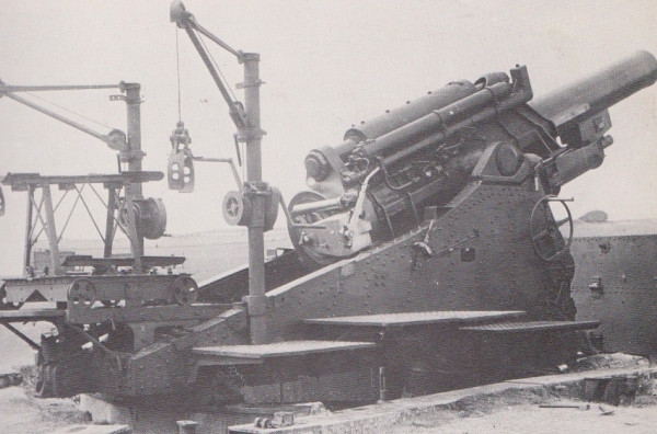
During the same period, a 12-inch railway howitzer was also introduced into service but of a completely separate design from the Elswick Ordnance Company. The railway gun was developed in Mks I, III and V variants and the siege gun was developed in Mks II and IV variants. The longer barrel and longer range Mk IV howitzer was introduced into service in 1917 and remained in use with home defence forces into WW2. A Mk IV is shown below, distinguished from the Mk II by a longer barrel and the hydraulic rammer on the top right of the cradle next to the hydraulic buffer.
Gun Design
The gun consisted of a rifled A-tube, muzzle stop ring, layers of steel wire, jacket, breech bush and breech ring. A number of layers of steel wire were wound over the A-tube from the breech to the muzzle stop ring. The jacket was then shrunk fit over the steel wire layers and the muzzle stop ring. The breech bush was screwed into the end of the A-tube and then the breech ring shrunk and screwed into the rear of the jacket. The jacket was fitted with two longitudinal projections forming the guides for it to recoil in the gun cradle.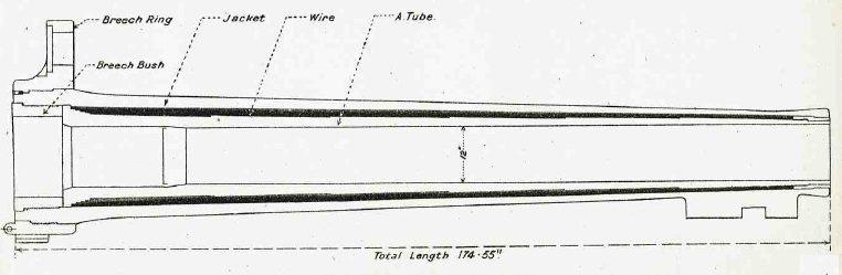
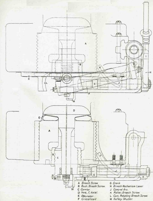
An interrupted thread breech screw of the Welin type was used that was supported on a carrier which was hinged on the right of the breech ring. The breech was fitted with a single motion breech: one pull of the lever on the right unlocked the breech screw and swung it into the loading position. The breech was sealed during firing by means of the obturator pad behind the mushroom shaped axial T-vent. Locking the breech, pressed the obturator pad into the coned rear of the breech. When the cartridge was fired, this forced the mushroom of the vent backwards compressing the obturator pad further against the sides of the breech and thus sealing it against the propellant gases.
The Mk II gun was designed to be fired using friction or percussion T-tubes. These T-shaped devices consisted of a vent plug filled with combustible pellets and a cross piece containing either a friction or percussion igniter with a loop for the firing lanyard. The vent plug was inserted into the axial T-vent at the back of the breech and was designed to seal the vent when the cartridge ignited.
The Mk IV gun was generally similar to the Mk II but with a bore of 17.3 calibres compared with 13.3 calibres for the Mk II. The MK IV gun had a similar breech and barrel construction to the Mk II.
Carriage
The design of the carriage for the 12-inch howitzer was similar to that of the 9.2-inch howitzer. The carriage allowed the howitzer to be fired with a maximum elevation angle of 65 degrees and allowed 30 degree of traverse to the left or the right. The gun was mounted in a cylindrical cradle in which it recoiled and was fitted with a recoil system that consisted of a hydraulic buffer and a hydro-pneumatic recuperator. The cradle was fitted with trunnions to allow it to elevate on the carriage. The Mk I carriage was designed to be used with the Mk II gun and the Mk II carriage was designed to be used with the longer Mk IV gun. One of the principal differences between the two marks of carriage was the fitting of a hydraulic rammer on the later Mk II carriage.
The gun could be elevated using the hand wheels on either side of the carriage. The gear on the left was ‘slow motion’ and elevated both the gun and sights. The gear on the right was ‘quick motion’ and was used to depress the gun for loading and to then raise it back up to the correct elevation for firing. The gun was elevated by means of an elevating arc under the cradle. However, the sights were rotated about the left-hand trunnion via a separate elevating arc to the left of the gun elevating arc. When the left-hand hand wheel was operated, both elevating arcs were moved together and so the sights elevated with the gun. However, by operating a foot lever on the right-hand side of the carriage, a clutch disengaged both the sight elevating arc and the left-hand elevating hand wheels from the gun elevating arc. This allowed the gun to be quickly depressed for loading without moving the sights and quickly returned to the correct elevation prior to firing.
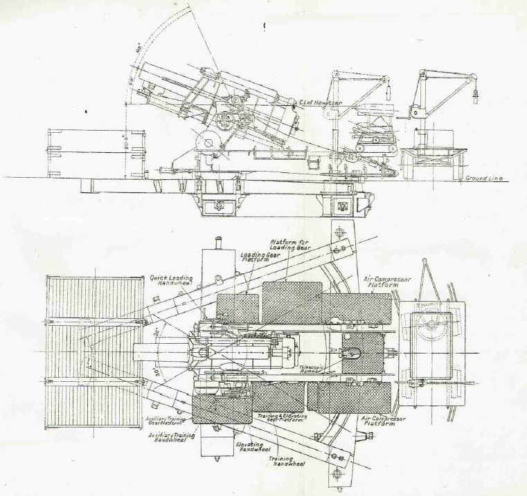
The carriage for the 12-inch howitzer differed from that of the 9.2-inch howitzer in using a bed that also combined the function of the separate holdfast used with the latter. The bed for the 12-inch howitzer consisted of two steel side girders converging at the front and connected laterally to the front and rear transoms which were of box design. The front transom supported the pivot block on which the carriage body pivoted while the rear transom carried the steel roller path on which the carriage body was traversed. It also carried the traversing rack. When deployed, the bed and transoms were sunk into the ground and a steel earth box was mounted on the front of the side girders to counter the carriage tipping backwards during firing. The earth box was filled with the order of 22 tons of earth.
The carriage was fitted with a number of platforms on either side and at the back to allow access to the gun by the gun detachment.
Shell Loading
With the 9.2-inch howitzer, it was possible for two men to manhandle each 290 lb shell onto the back of the carriage prior to it being hoisted and rammed into the breech. However, for the 12-inch howitzer, the 750 lb shells were too heavy to be moved by hand and therefore cranes had to be used to handle them. The shells were loaded into the gun using a projectile trolley that ran on rails on the back of the carriage body. Shells were provided to the gun on an ammunition trolley that was wheeled to the back of the carriage and then a crane mounted on the right of the carriage was used to hoist the next shell on to the projectile trolley.
On the Mk II howitzer, the shells were loaded with the gun at an elevation of 2 degrees. With a shell hoisted on to the top of the projectile trolley, it was then wheeled forward to place the shell at the opening of the breech after which it was rammed home manually followed by the cartridge. The trolley then had to wheeled to the back of the carriage and locked in position before the gun could be fired.
However, the Mk IV howitzer made use of a hydraulic rammer. This took the form of a telescopic rammer at the back of the carriage under the projectile trolley that was powered by a hydro-pneumatic accumulator mounted on the cradle to the right of the recoil buffer. When using the hydraulic ram, the gun was set at an elevation angle of 19.5 degrees and the shell then tilted on the lower tray of the projectile trolley to the same angle. The trolley was then wheeled forward to place the shell at the breech opening before the hydraulic rammer was activated.

The rammer accumulator consisted of a hydraulic cylinder filled with oil with a replenishing tank at the front and a high pressure cylinder mounted above it containing a floating piston. The hydraulic cylinder piston rod was connected to a lug on the breech and, during recoil, the piston was pulled backwards forcing oil through a delivery valve into the back of the HP cylinder compressing the air in front of the floating piston which was initially pressurised to 500 psi. When the recoil ended and the gun was run out, the delivery valve closed preventing oil from flowing back from the HP cylinder with the oil behind the hydraulic piston replaced from the replenishing tank.
The rear of the HP cylinder was connected to the rammer control valve on the back of the carriage via flexible pipes. With the projectile trolley and shell run forward to the breech, moving the rammer control valve to the ‘Ram’ position allowed the compressed air in the HP cylinder to force oil into the rear of the hydraulic rammer forcing the ram and shell forward. When the control lever was moved to the ‘Withdraw’ position, this forced oil into the front of the rammer forcing the ram back into its cylinder. The excess oil from the rammer was forced back into the replenishing tank on the accumulator. 
Recoil System
The recoil mechanism consisted of a hydraulic buffer mounted on the cradle above the gun and a hydro-pneumatic recuperator mounted beneath it. The hydraulic cylinder recoiled with the gun with ribs fitted to enable it to slide in grooves on the cradle. The hydraulic piston remained stationary during recoil attached via a rod to the cradle and oil had to flow past through a port in the piston resisting its flow and absorbing the recoil energy. The total length of recoil was 50 inches. A control rod was fitted behind the piston that entered a narrow chamber as the gun was run out and, by having to displace the oil there, brought the gun to a gentle stop.
The gun was fitted with a hydro-pneumatic recuperator mounted under the gun. The recuperator consisted of an air cylinder that remained stationary on the cradle when the gun recoiled. An hydraulic ram was connected to a bracket under the muzzle of the gun and was forced past a seal into the end of the recuperator cylinder when the gun recoiled. A long hollow floating piston was mounted inside the ram and air cylinder with oil in the ram in front of it. The main purpose of the floating piston was to ensure a positive pressure on the oil side of the piston seals to prevent air leakage. The diameter of the ram was less than that of the air cylinder so that, as the ram moved into the cylinder, it left a space between it and the cylinder into which oil had to flow. The net effect of this was that, when the gun recoiled back 50 inches along with the ram, the floating piston only moved 39.8 inches. The front of the floating piston was formed into a rod that passed through a seal in the front of the ram and provided a visual indication of how much oil was in the recuperator. When run out, a pressure of about 500 psi was maintained in the HP cylinders.

Sights
The sight supporting bracket was fixed to a bracket that rotated on the left-hand gun trunnion and given the same elevation angle as the gun via a sight elevating arc under the cradle. The sights were oscillating or reciprocating in order to compensate for the gun trunnions not being perfectly level. This type of tilt caused the vertical plane containing the projectile’s trajectory being rotated in azimuth in the direction of the lowest trunnion. To compensate for this, an oscillating bracket was mounted on the sight supporting bracket that could be tilted about a pivot that was parallel to the gun axis. By using the cross bubble to make the oscillating plate vertical, this ensured the sights were in the same plane as the projectiles.
The sights themselves were mounted on a range bracket that pivoted in elevation on the oscillating bracket. A hand wheel was provided to rotate the range bracket with a range dial indicating the elevation angle from 0-65 degrees in 5 minute steps. The range bracket mounted a rocking bar sight and a carrier for the dial sight with a cam mechanism provided for automatically adjusting the sights for the angle of drift as a function of elevation angle. A longitudinal level was fitted in order to provide a means for determining the quadrant elevation of the sight.
The range bracket was also pivoted horizontally on the range bracket with a scale and adjuster provided to allow up to 5 degrees of deflection to be applied to the sight to the left or right. The rocking bar provided open sights consisting of a front acorn and notched leaf at the rear. It could also mount a No. 4 sighting telescope.
For indirect fire, the panoramic No. 7 dial sight was used. The required quadrant elevation for the gun was determined from the estimated target range and the use of range tables. This elevation angle was set on the range dial and then the gun elevated until the longitudinal level was levelled. The required target bearing was determined using maps and defined in terms of an offset bearing from the gun’s aiming point. The aiming point was a known feature in the landscape that could be clearly seen in the dial sight and could be in front or behind the gun. The required target offset bearing was set on the sight and then the gun traversed until the gun’s aiming point was centered in the sight at which point the gun was aligned with the target.

Gun Transport
The 9.2-inch howitzer was transported in 3 loads: the first included the gun; the second included the carriage; and the third included the bed. The 12-inch howitzer had to be transported in 6 loads using specially designed carriages. The loads consisted of the gun, cradle, carriage body, bed and earth box, front transom and pivot block, and rear transom and roller path. All the carriages used traction engine steel wheels and had to towed via mechanised transport.
Ammunition
The BL 12-Inch Howitzer was designed to fire high explosive shells with a weight of 750 lb. It used separate bagged cartridges with igniter powder sewn into it base. This was set off using either a friction T-tube or a percussion T-tube inserted into the rear of the breech with the flash travelling down the centre of the axial T-vent to set off the cartridge.

The shells were made of forged steel with the Mk I-V shells having a 2 calibre radius head and the later marks have a 4 calibre radius head. A No. 44 direct action fuze or No. 101 percussion fuze was used with the shells.

BL 12-Inch Howitzer Mk II Specifications
- Overall Height: 8 ft 10 inches (gun horizontal)
- Overall Length: 23 ft 4 inches (gun horizontal and excluding bed)
- Overall Width: 12 ft 4 inches including platforms
- Total Weight of howitzer: 34 tons 2 cwt 89 lb; 61 tons 14 cwt 26 lb on transport carriages
- Length of Gun Barrel: 14 ft 6.5 inches
- Length of Bore: 13 ft 4 inches
- Bore: 12 inch
- Weight of Gun & Breech: 7 ton 14 cwt
- Muzzle Velocity: 1261 fps
- Maximum Range: 11,350 yds
- Recoil System: Hydro-pneumatic
- Maximum Recoil: 50 inches
- Rifling: Polygroove with plain section
- Length of Rifling: 11 ft 6 inches
- Twist: Right-hand 1 turn in 15 calibres
- Grooves: 60
- Firing Method: Friction or percussion T-tube
- Elevation: 20° to +65° for firing; 3° for loading
- Traverse: -30° left to +30° right
BL 12-Inch Howitzer MK IV Specifications
- Overall Height: 8 ft 10 inches (gun horizontal)
- Overall Length: 23 ft 4 inches (gun horizontal and excluding bed)
- Overall Width: 12 ft 4 inches including platforms
- Total Weight of howitzer: 44 tons 6 cwt 31 lb; 73 tons 12 cwt on transport carriages
- Length of Gun Barrel: 18 ft 6.5 inches
- Length of Bore: 17 ft 3.6 inches
- Bore: 12 inch
- Weight of Gun & Breech: 9 ton 2 cwt 56 lb
- Muzzle Velocity: 1522 fps
- Maximum Range: 14,350 yds
- Recoil System: Hydro-pneumatic
- Maximum Recoil: 50 inches
- Rifling: Polygroove with plain section
- Length of Rifling: 14 ft 6.75 inches
- Twist: Right-hand 1 turn in 20 calibres
- Grooves: 60
- Firing Method: Friction or percussion T-tube
- Elevation: 20° to +65° for firing; 19.5° for loading
- Traverse: -30° left to +30° right
![]()