

In the early years of the 20th Century, the French Army doctrine was to rely heavily on the Canon de 75 Mle 1897 to provide the mobility and fast rate of fire they considered necessary in modern warfare. However, they also invested in the Canon de 155 Mle 1904 CTR Rimailho to provide a heavier field gun with a high rate of fire. Unfortunately, as only 104 of these were available at the outbreak of WW1, the obsolete Canon de 155 L Mle 1877 had to be bought out of retirement in order to provide enough 155 mm howitzers to meet the Army’s needs.
By 1915, it was clear that in the type of trench warfare that had developed after the first year of war, the Mle 1877 could not provide the high rate of fire required and the Mle 1904 was too short ranged. The French Government therefore turned to both FAMH (often referred to as St Chamond from where they were based near Lyon) and Schneider and considered the heavy howitzers they had developed for export – St Chamond had developed a 150 mm howitzer for Mexico and Schneider had developed a 152 mm howitzer developed for the Russian Army. Modified versions of both of these were adopted as the Canon de 155 C Mle 1915 St Chamond and the Canon de 155 C Mle 1915 Schneider, respectively, where the ‘C’ stood for court or short in English.
Four hundred of the St Chamond howitzers were ordered which were officially designated the C15F but they were not delivered until 1916. They proved not to be as successful as the Schneider design and, although FAMH developed an improved version of the howitzer, after the original order was completed production at C15F largely switched to the Schneider design.
Carriage
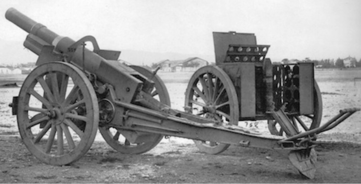
The C15F used a box trail with two side arms in the front half in order to provide space for the gun to recoil at higher elevation angles. The trail was provided with a shield to protect the gun crew and was provided with a spade and traversing lever at the rear. It was mounted on two standard wooden wheels with steel tyres with brake blocks provided at the front.

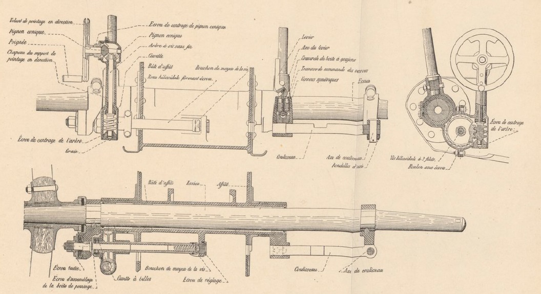
In a similar way to comparable German heavy field guns of the time, the C15F gun pivoted at the rear of the cradle. This gave the advantage that the height of the breech changed very little when the gun was elevated making it easier to load shells but required a pneumatic strut underneath to help support the weight of the unbalanced gun and cradle. The gun was elevated via a pair of hand wheels on opposite sides of the carriage that rotated a pinion via a gear train that engaged with a large elevating arc beneath the gun cradle. The pinion and the top of the elevating arc can be seen in the middle of the lower part of the diagram below. On the right-hand side of the cradle, a tangent elevation drum (top right of diagram) was provided graduated from 0 – 800 in units of 1/20th of a degree.

As with many French artillery field pieces, the C15F provided -3 to +3 degrees of traverse by moving the front of the trail along the wheel axle. The upper hand wheel on the left-hand side of the cradle was used to traverse the gun. Via a gear train, this rotated a worm wheel that also acted as the nut on a horizontal screw jack with one end fixed via a bracket to the wheel axle and the other end fixed to the gun cradlet. Thus, as the hand wheel was turned, the screw jack moved the cradle either way along the wheel axle traversing the gun.
The gun was transported by attaching it to a 2-wheeled limber pulled by 8 – 10 horses. During transport the gun was locked in the full recoil position to even up the weight distribution between the two pairs of wheels.
![]()
Gun Design
The C15F gun was 2.76 m or 17.8 calibres long and of built up construction with a jacket shrunk on to the rear half of the rifled tube. The breech mechanism was then screwed on to the rear of the barrel and the jacket and had a lug underneath at the rear to connect to the recoil mechanism. A loop was shrunk on to the rifled tube half way between the muzzle and the front of the jacket to support the rails that allowed the gun to slide along the top of the cradle during recoil.

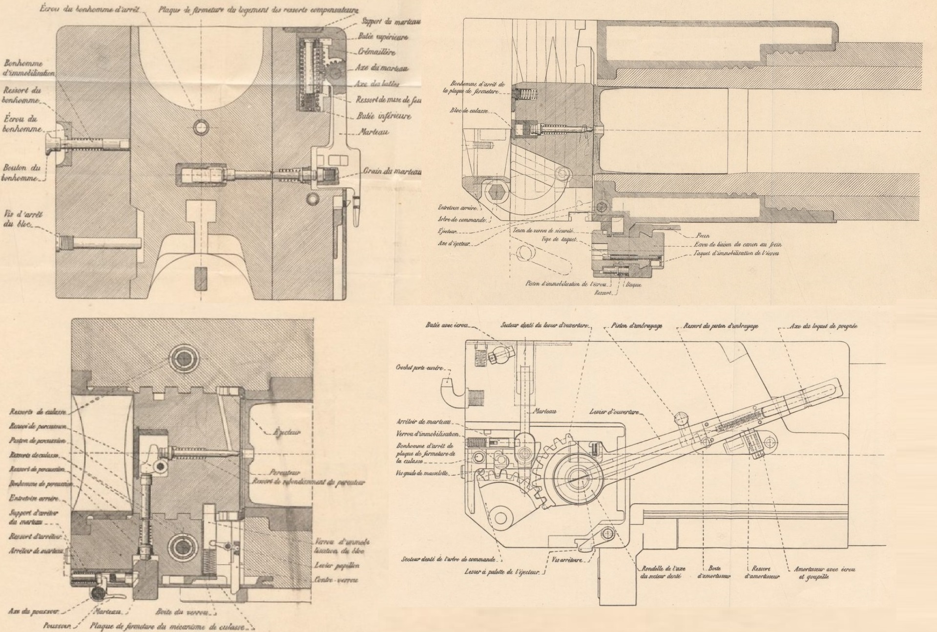
The C15F used a vertical sliding breech which was raised and lowered using a lever on the right of the breech. Since brass cartridge cases were used, these were fired via a firing pin in the centre of the breech which was struck indirectly via an external spring loaded hammer on the right-hand side of the breech that was cocked by hand and then released to fire the round. Any empty case was ejected automatically when the breech was opened.
A loading tray was clipped to the end of the breech to allow the next round to be loaded on it before behind pushed into the breech.
Recoil System
The C15F incorporated a recoil system made up of 3 separate cylinders mounted together and slung under the cradle on which the gun recoiled. The middle cylinder housed the hydraulic buffer with the two outer cylinders forming two spring recuperators. At the rear of the recoil system was a large cross piece that attached the mechanism to a lug under the breech.
The hydraulic buffer consisted of an oil filled cylinder with a piston on the end of a hollow rod connected at the rear to the cross piece. When the gun recoiled, it forced oil past the piston through small constrictions which helped to absorb the recoil energy in combination with the springs in the recuperators. Inside the hollow piston rod was a control rod connected to the front of the hydraulic cylinder whose purpose was to bring the gun to a gentle stop as the recuperators brought the gun back to battery after the recoil ended.
Each recuperator consisted of a hollow rod connected to the rear cross piece with a large diameter flange at the front which pushed against two concentric springs as the gun recoiled. When the recoil had been brought to a stop, the springs then pushed the gun back into battery. In the updated version of the gun, the spring recuperators were replaced by pneumatic recuperators and the distinctive air reservoirs can be seen projecting forward of the gun cradle.

The maximum recoil distance of the gun was 1.30 m.
Sights
The C15F sights were developed before the adoption of an effective dial sight or panoramic sighting telescope became available and instead used a collimator on top of a rotatable column as the main sighting device. This could be tilted fore-aft on its mounting bracket to restore it to the vertical when the gun was elevated. However, this sighting system did not incorporate a facility for setting the elevation angle for the gun which had to be done separately using a Mle 1888 field clinometer mounted on top of the breech. Oddly, in contrast with many other artillery pieces of the time, the sights were not mounted on the gun trunnion but instead were mounted 200 mm in front of the left-hand trunnion complicating their design.
The C15F sights were reciprocating in order to compensate for the carriage wheels not being level which was the norm. Ignoring the spin drift of the shells and the effect of cross winds, the trajectories of the shells will lie in a vertical plane through the gun. However, if the wheels are not level, the trajectory plane will be rotated in azimuth away from the centreline of the carriage in the direction of the lowest wheel degrading the accuracy of the howitzer especially at high elevation angles. In order to compensate for this effect, it is necessary to tilt the sights sideways in order to restore them to same vertical plane as the gun.
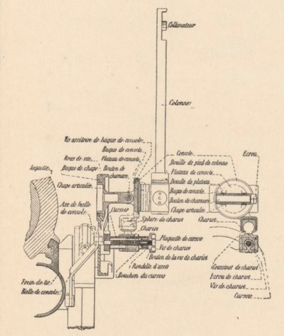
The sights were mounted on a curved sight arm (bras de site) whose upper end was fixed to the left-hand trunnion mounting and whose lower end was fixed to the end of elevating pinion shaft bracket. The sight arm had a small vertical projection to support the sight mounting bracket (chape articulie) that was able to rotate about an axis perpendicular to the sight arm. The sight assembly itself was mounted on a reciprocating bracket (console) that could pivot on the sight mounting bracket via a hinge bolt (boulon de charniere). Attached to the underneath of the sight mounting bracket was a perpendicular screw driven trolley (chariot mounted on cursoir) linked to the reciprocating bracket via a ball joint. The lateral position of the trolley could be altered via a knob on the outside of the screw mechanism which had the effect of tilting the reciprocating bracket about the hinge bolt. The inside end of the screw mechanism was linked to a fixed point on the cradle via a rod (bielle de console) that allowed rotation at either end.
The complicated mounting arrangement for the sights was designed to ensure that the reciprocating bracket hinge bolt remained parallel to the gun as its elevation angle was changed. In this way, it meant that tilting the reciprocating bracket could bring the sights back into the same vertical plane as the gun thus compensating for the carriage wheels not being level. However, the sights were not equipped with levelling bubbles which meant that the collimator had to be tilted into the vertical plane in both planes using the field clinometer.
Had the sights been mounted on the gun trunnion, the design of the reciprocating bracket would have been relatively simple. However, because the sights were mounted 200 mm in front of the left-hand trunnion, a parallel motion mechanism had to be used to ensure the sight mounting bracket rotated through the same angle as the left-hand trunnion – that way, the reciprocating bracket hinge bolt always remained parallel to the gun. The parallel motion mechanism was driven by the cradle rod which was arranged to be parallel and of equal length to the line running between the centre of the trunnion and the centre of the sight mounting bracket bearing. The other two sides of the parallelogram making up the mechanism were the part of the cradle between the trunnion and the attachment point of the cradle rod, and the part of the sight mounting bracket between its rotation bearing and the outer end of the cradle rod.
Ammunition
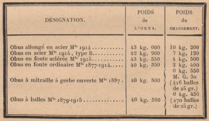
The C15F used brass cartridges with 6 different charges (00, 0, 1,…5) and muzzle velocities available. The following projectiles were used where the bottom two projectiles are Shrapnel shells and the rest are high explosive.
Canon de 155 C Mle 1915 St Chamond Specifications
- Length: 5.52 m
- Maximum Width: 1.52 m
- Wheels: Wooden 1.33 m in diameter
- Weight of Gun & Carriage: 2860 kg
- Length of Gun: 2.76 m or 17.8 calibres
- Bore: 15.5 cm
- Muzzle Velocity: 370 m/s (FA 1915 shell)
- Maximum Range: 9,300 m
- Trail: Box trail
- Recoil System: Hydro-pneumatic
- Maximum Recoil: 1.30 m
- Rifling: Unknown
- Length of Rifling: 2. 255mm or 14.5 calibres
- Twist: Right-hand
- Grooves: Unknown
- Firing Method: Percussion
- Elevation: 0° to +40°
- Traverse: -3° left to +3° right
![]()