

The Canon de 155 C Mle 1917 was built by the French firm of Schneider where the C stood for Court or short in English. It was basically an earlier Canon de 155 C Mle 1915 Schneider but with the breech changed from using metal cartridges to bagged charges in order to make operating the gun less costly. The earlier gun itself was based on the 152 mm M1910 howitzer developed for the Russian Army by Schneider which used the carriage and recoil system that was later used by the Canon de 105 L Mle 1913. Modifying the carriage to mount a 155 mm howitzer for the French Army was relatively straightforward.
The US army had not developed their own heavy field gun for use during WW1 and therefore adopted both British and French weapons as a result. This included the British 8 inch and 9.2 inch howitzers, the French 155 mm Mle 1917 Schneider as a medium field howitzer and the 155 mm Mle 1917 GPF as a long range heavy field gun.
The French manufactured 155 mm Mle 1917 Schneider used by the US was designated the 155 mm Howitzer Materiel M1917. However, when the gun was subsequently manufactured in the US, it was then designated as the 155 mm Howitzer Materiel M1918. It should be noted that the US followed the French approach of using the word ‘materiel’ to describe a complete artillery piece. The original M1917 & M1918 howitzers were designed for slow speed transport and used wheels with solid rubber tyres on the carriage. For later higher speed transport, the carriage was then modified with improved brakes and wheels fitted with pneumatic tyres. The M1918 remained in front line US service until replaced by the 155 mm Howitzer M1 from 1941.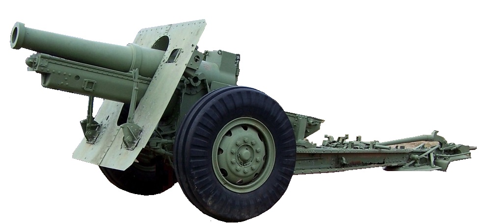
Gun Design
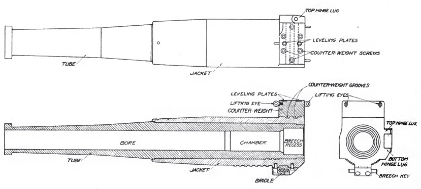
The gun was 91 inches or 15 calibres long and was of built-up construction as was normal during the early part of the 20th century. The gun consisted of a rifled tube with a chamber for the projectile at the rear behind which was an interrupted threaded section for the breech screw. A jacket was shrunk over the rear portion of the tube with fittings to support the breech mechanism. The trunnions on the cradle were set quite far back resulting in an unbalanced gun. Rather than fitting equilibrators to support this weight, the M1918 used a distinctive looking balance weight bolted above the breech.
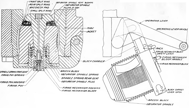
An interrupted screw breech was used with a single motion lever that, when operated, rotated the breech screw to unlock it before swinging it clear of the breech opening. The sealing of the breech (obturation) was achieved by using a mushroom shaped obturator that fitted into the front of the breech block. Between the mushroom head and the front of the breech screw was a sealing ring such that, when the breech was closed, the seal was pressed against the tapered rear of the combustion chamber. When a cartridge was fired, the combustion chamber pressure pushed the obturator slightly backwards further compressing the sealing ring against the side of the chamber completely sealing it.
The M1917 & M1918 guns used bagged charges which were ignited using a percussion cartridge or primer that fired through a vent in the centre of the obturator. This cartridge was set off by a striker that was hit by a hammer at the rear of the breech that was cocked manually and released via a lanyard.
Carriage
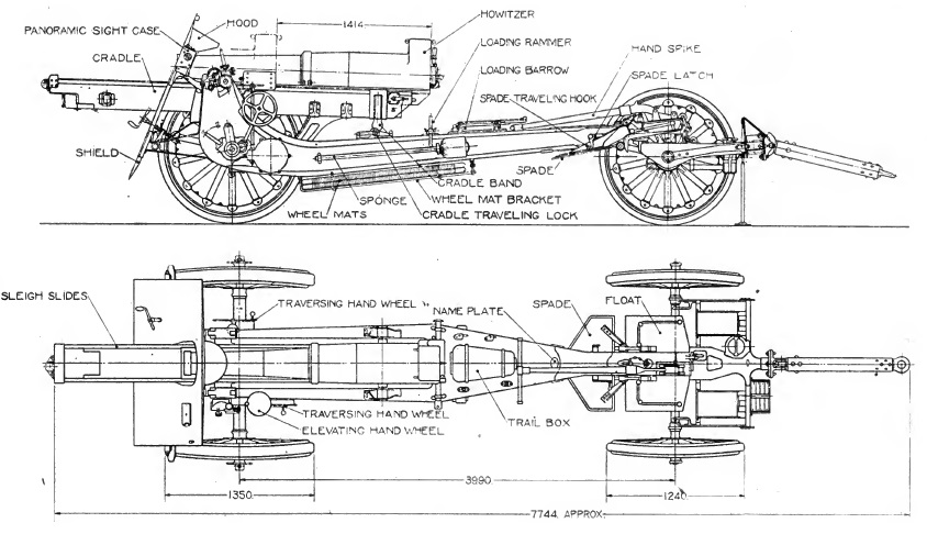
The M1917 & M1918 carriages consisted of a box trail with side arms in the front half that allowed space for the gun to recoil at higher elevation angles. Although the 155 mm Mle 1917 used a curved shield, the M1918 used a simpler flat shield mounted on the front of the trail to protect the gun crew with a hinged opening to allow for forward observation of the gun sights. The rear of the trail was provided with a spade to stabilise the gun during firing which was supplemented by brake shoes acting on the front of the wooden wheels operated by a rotary handle on the front of the shield. The wheels were fitted with solid rubber tyres for higher speed transport.
The cradle pivoted on trunnions running in bearings at the top of the front of the trail with traverse provided by moving the trail sideways by up to 3 deg either side along the wheel axle. A traversing hand wheel was provided on both sides of the trail for this purpose that each rotated a screw thread inside a tube in front of the axle. This in turn moved a nut on the thread that was attached to the wheel axle resulting in the front of the trail being moved sideways along the axle.
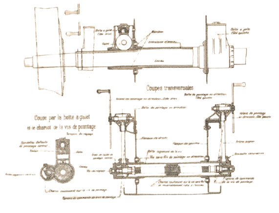
The gun was elevated by means of a pair of large toothed arcs fitted either side under the gun cradle. An elevating hand wheel was provided on the left-hand side of the carriage which rotated a pair of elevating arc pinions via a gear train to provide fine adjustment of the gun’s elevation.
Transport
The gun was originally transported by either 8 horse or via motorised tractor using a two wheel limber as shown. To balance the gun between the two sets of wheel, it was locked in the full recoil position. In the 1930’s, metal wheels with pneumatic tyres and air brakes were installed on the M1918A1 to facilitate high speed mechanised towing that also dispensed with the need to use the limber.
Recoil System
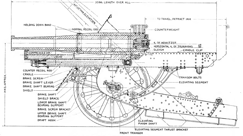
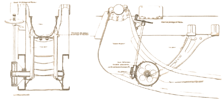
Unlike the German and British field howitzers employed in WW1 which used hydro-spring recoil systems, the 155 mm Mle 1917 and M1918 used a much more sophisticated hydro-pneumatic recoil system. The recoil system was contained within the cradle on a recoil sleigh to which the gun was attached which recoiled along runners either side of the cradle. The cradle extended some distance behind the breech to allow the gun to be fully supported for the full length of recoil.
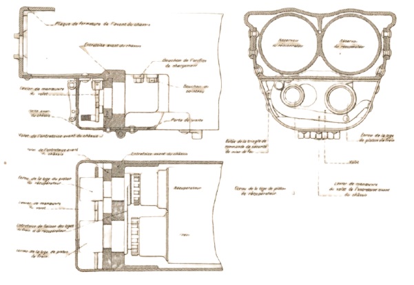
Within the recoil sleigh, there were two cylinders in the lower part with the right-hand one forming the hydraulic buffer and the left-hand one forming the recuperator liquid cylinder. At the front above these cylinders were 2 high pressure (HP) cylinders for the recuperator. The hydraulic buffer is shown at the bottom of the cutaway (French) drawing below which is drawn for clarity with the buffer and the recuperator one above the other rather than side by side.
The hydraulic cylinder was filled with oil and contained a piston on the end of a hollow rod attached to the front of the cradle so that, as the gun recoiled, the cylinder moved backwards while the piston stayed still. The piston contained small ports to restrict the flow of oil past it during recoil and, in so doing, absorbed a large part of the recoil energy. The piston rod was also filled with oil and contained a rod attached to the rear of the recoil sled. The purpose of this inner hydraulic buffer was to absorb the remaining energy in order to bring the gun to a gentle stop when it was returned to battery.
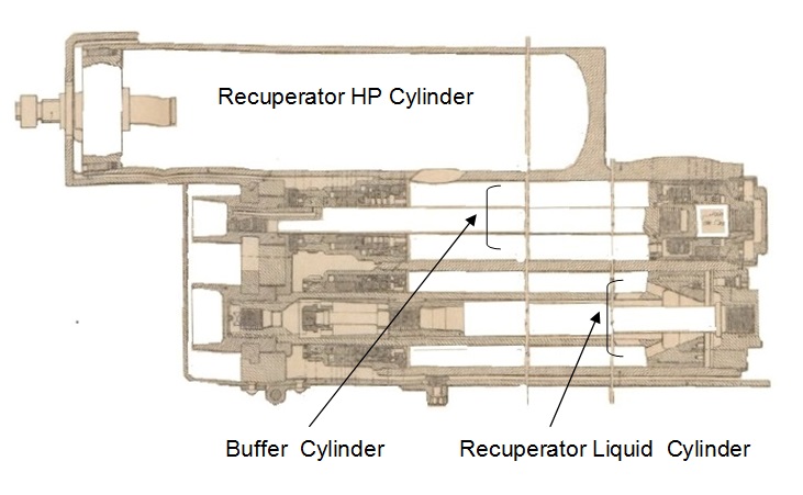
The recuperator is shown just below the large reservoir in the cutaway drawing above and was responsible for absorbing some of the recoil energy and then using this to return the gun to battery after the recoil ended. The recuperator consisted of a liquid cylinder in the lower part of the recoil sled, which recoiled with the gun, and a piston on the end of a rod fixed to the front of the cradle. As the cylinder moved backwards, the oil in front of the piston was forced into the two large HP cylinders at the front of the recoil sleigh thus compressing the air inside. Once the recoil had stopped, this increased air pressure then forced the gun forward back into battery. The ambient air pressure was maintained at 500 psi.
The M1917 & M1918 did not have to use a variable recoil system to restrict the length of recoil as the gun was elevated as there was always sufficient clearance for the recoiling breech above the ground. The maximum recoil length of the gun was 49 inches.
Sighting
The sights were mounted on a bracket fixed to the end of the left-hand gun trunnion and therefore elevated with the gun. As with nearly all howitzers, the sights were reciprocating to allow them to compensate for the carriage wheels not being level, which was the norm. Any trunnion tilt caused the vertical plane through the gun to be rotated in azimuth in the direction of the lowest trunnion resulting in a large sighting error if not compensated. To eliminate this effect, the sights were mounted on a reciprocating bracket that could be tilted sideways about an axis maintained parallel to the gun to put the sights back into a vertical plane parallel to that of the gun. This tilting was performed using the knurled knob and the cross-level bubble at the front of the sight.
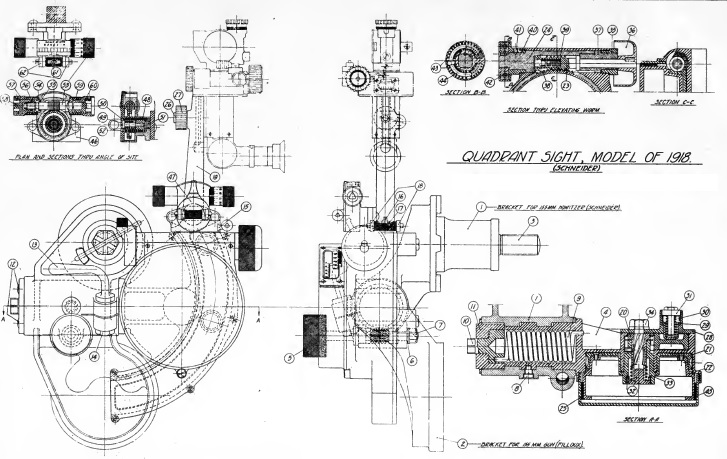
The tangent elevation was set on the elevation drum using the elevating knob at the rear of the sight. The elevation drum was graduated from 0 – 800 mils (0° – 45°); setting a tangent elevation angle on the sight, tilted the sights forwards by that angle. The sight mount also incorporated a sight clinometer or angle of sight level (as the US called it) that allowed the angle of sight to be set. It was graduated in 100 mil intervals numbered from 0 to 6 with setting 3 corresponding the the clinometer being level. The micrometer was graduated from 0 – 100 in 1 mil intervals. In practice, the quadrant elevation set on the gun was the sum of the angle of sight and the tangent elevation settings. Once set on the sight, the gun was then elevated until the clinometer bubble was level. The quadrant elevation could also be set or checked using a gunner’s quadrant place on a flat on top of the breech.
The M1918 howitzer was mainly used for indirect fire using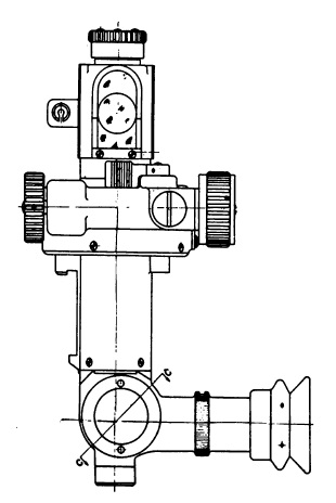 the M6 panoramic telescope in laying for direction. This was a four power telescope with a fixed eyepiece at the bottom and a viewing head at the top that could be rotated through 360°. The azimuth scale provided was graduated in 100 mil intervals from 0 – 32 mils (0° – 180°) in either direction with the micrometer graduated from 0 -100 in 1 mil intervals. The telescope was also provided with an elevation adjustment for the angle of sight.
In indirect fire, the target direction was specified in terms of an offset bearing from an aiming point defined for the gun which could be a prominent feature in the landscape or specially set up aiming posts that could be in front of the gun, behind the gun or to one side. To aim the gun at the target required the offset bearing to be set on the sight and then the gun traversed until the aiming point was centred in the sight.
Ammunition
The M1918 used bagged charges with 7 different charge levels (1,…,7) and muzzle velocities. The cartridges were made up of a base charge with 3 oz of black powder sewn into the base that was ignited via a percussion tube or primer inserted into the rear of the breech. The 7 charge levels allowed the howitzer to cover 7 different range zones. The maximum charge 7 consisted of 13.9 lb of smokeless propellant and achieved a muzzle velocity of 1,480 ftp and a maximum range of 12,300 yds when firing a HE shell
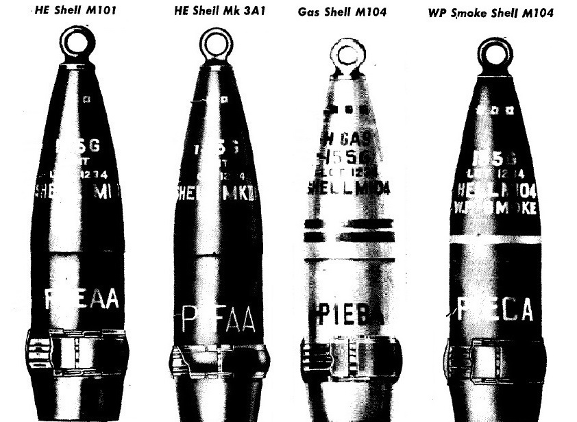
TheM1917 & M1918 originally used French designed shells characterised by having 2 narrow driving bans with the later shells having a single wider driving band. By WW2, 5 different types of shell were fired by the M1918: high explosive (HE), armour piecing (AP), gas, smoke and shrapnel. These were used with super-quick and delay fuzes M51, M46 & M47 together with the time & percussion M1907 fuze providing up to a time delay of 45 seconds.
The older Mk III HE weighed 95 lb, was 25.54″ long and was filled with up to 15 lb of TNT or Amatol. The newer M101 HE shell weighed 95 lb, was 26.79″ long and was filled with a bursting charge of up to 16 lb of TNT or Amatol. The M104 gas shell was of similar size and weight to the HE shell and contained a chemical filling of 11.7 lb together with a small bursting charge. The M104 smoke shell weighed 99 lb, was 26.82″ long and contained a phosphorous filling of 16.9 lb together with a small bursting charge. All the shells had a 11 calibre radius head and were boat tailed.
155 mm Howitzer Materiel M1918 Specifications
- Length: 18 ft 9 inches
- Maximum Width: 60 inches
- Wheels: Wooden 53 inches in diameter
- Weight of Gun & Carriage: 7,600 lb
- Length of Gun: 91 inches or 15 calibres
- Bore: 155 mm
- Muzzle Velocity: 1,480 fps
- Maximum Range: 12,300 yds
- Trail: Box trail
- Recoil System: Hydro-pneumatic
- Maximum Recoil: 51 inches
- Rifling: Uniform 1 turn in 25 calibres
- Length of Rifling: 68.4 inches or 11.2 calibres
- Twist: Right-hand
- Grooves: 48
- Firing Method: Percussion
- Elevation: 0° to +42°
- Traverse: -3° left to +3° right
![]()