

During the 2nd Boer War (1899-1902), the main field gun used by the Royal Horse Artillery (RHA) was the breech loading 12-Pdr BL 6 Cwt Gun that was introduced into service in 1894. It used the smokeless propellant Cordite and fired shrapnel shells to a maximum range of 6,000 yd. Although it was equipped with elementary devices to limit the recoil of the gun, it still needed to be re-laid before firing the next shell.
However, in 1897, the French adopted the famous Matériel de 75 mm Mle 1897 or French 75 that incorporated the first effective hydro-pneumatic recoil system for a field gun. This system completely absorbed the recoil of firing and automatically returned the barrel ready for the next round allowing a maximum of at least 20 rounds a minute to be fired out to a range of 9,300 yds. The introduction of the French 75 more or less rendered every other field gun obsolete. In British terminology at that time, this type of gun was referred to as quick-firing (QF). This was not only because of the recoil system but also because brass cartridges were used that provided the necessary obturation (sealing of the breech) and removed the need to swab out the breech each time a round was fired.
In 1901, the Special Committee on Horse and Field Artillery Equipment was established with Cabinet approval chaired by Major-General George Marshall who was a former artillery commander in South Africa. He brought together other artillery commanders with war experience to establish the requirements for quick-firing field guns covering both a horse artillery gun and a field artillery gun. Of the entries received, 5 were selected for the horse artillery and 3 for the field artillery and their makers were then invited to submit prototypes.
These were tested in 1902 but none was found to satisfactory. The makers were therefore called to a conference and agreed to collaborate on a composite design that eventually resulted in using the Armstrong gun, the Vicker’s recoil system and the Royal Ordnance Factory Woolwich sighting and elevating gear and ammunition carrying. Trials of the composite guns took place in 1903 and the guns were accepted into service in 1904. The Royal Field Artillery were provided with the 3.3 inch calibre 18-Pdr QF Gun while the Royal Horse Artillery were provided with a 3 inch calibre 13-Pdr QF Gun but with the barrel shortened by 2 feet and the weight reduced by 589 pounds.
The 13-pdr was only designed to fire shrapnel shells. Although the gun saw considerable action at the start of WW1, the most famous involving L-Battery RHA at Néry, once trench warfare set in, the 13-pdr and the cavalry it was designed to accompany saw relatively little action.
Gun Design
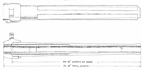
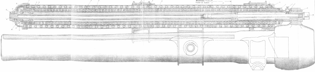
The Mk I gun barrel was made up of a rifled A-tube extending from the rear end of the chamber to the muzzle. Over the rear portion of the A-tube was wound successive layers of steel wire and then a jacket was shrunk over the wire and the A-tube. The jacket was fitted with longitudinal projections on each side to form guides as it recoiled within the gun cradle. The breech ring was screwed into the end of the jacket.
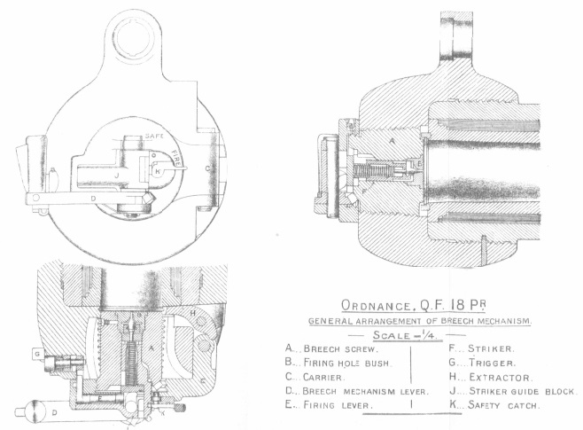
The gun fired fixed rounds with brass cartridges and was fitted with a ‘Single Motion Breech Mechanism’. This required one pull of the operating lever to unlocked the interrupted thread breech and to swing this out of the way to enable a new round to be loaded. After loading, one push of the lever then closed the breech and locked it into position. The round was fired by a striker operated by a firing lever on the left of the gun normally operated by a lanyard. The breech was fitted with an extractor that automatically operated when the breech was opened and ejected any spent cartridge.
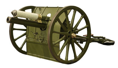
Carriage Design
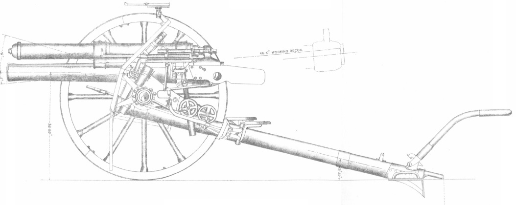
The carriage was fitted with a tubular steel trail with a spade and traversing lever on the end. The trail was attached to the axletree via a bracket that also served as the pivot for the carriage body (saddle). The axletree was fitted with 5 foot wooden wheels with 3-inch steel tyres. The gun shield was attached to the axle tree. Leather cases were provided on the shield for the dial sight, field clinometer, sight clinometer, spare parts, fuze keys, shovel, aiming posts, breech and muzzle covers, oil can, fuze indicator, tool case and telescope. The carriage was fitted with brake shoes on the ends of arms that pivoted off the side of the trail to act against the rear of the wheels. They were operated by a brake handle at the front of the carriage.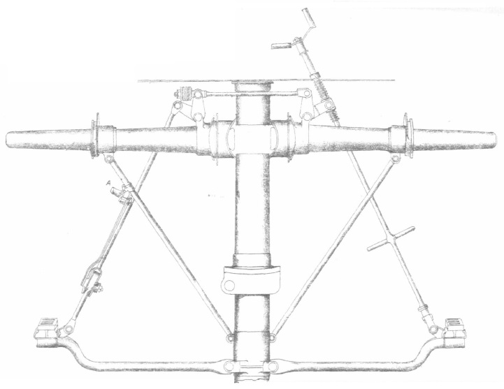
The carriage body consisted of two triangular shaped frames connected by transoms and was fitted with a bearing to allow it to pivot on the axletree during traversing . The cradle was made of bronze with trunnion arms to allow it to pivot in elevation in bearings on the carriage body. It had an opening and guides in the lower part along which the gun recoiled. In the upper part it had an opening for the spring case that was fixed to it.
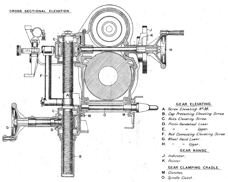
The rear of the carriage body was attached to a screw jacket fixed to the trail that allowed the gun to be traversed by up to 4.5° to either the left or right. Traversing was achieved using the traversing hand wheel on the left of the carriage. The rear of the carriage body was also equipped with a clamp activated by a lever and used when travelling.
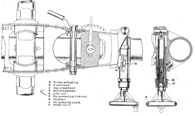
The gun was elevated via an elevating screw on the left-hand side of the cradle that was double ended. The gun layer’s hand wheel raised or lowered the elevating screw and in so doing raised or lowered both the sight bracket and the gun and cradle. This hand wheel allowed the angle-of-sight (AS) to be set on the gun. The hand wheel on the right-hand side left the sight bracket unaltered but independently raised or lowered the gun and cradle – this therefore applied tangent elevation (TE) to the gun. The right hand wheel was provided with a range drum that was graduated on its face to 6,300 yd by means of a pointer in 100 yd intervals. The periphery of the drum was graduated to 16 degrees in 10 minute intervals. In practice, the sum of the AS and TE was the quadrant elevation (QE) for the gun.
Limbers
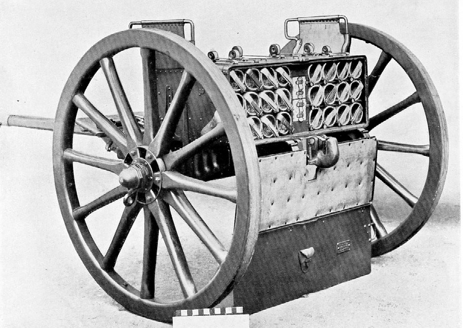
The new guns were fitted with standard 5 foot wooden wheels and were towed behind a limber that was pulled by 6 horses. The carriage limber carried 32 rounds of ammunition and other stores and was normally deployed in the field to the left of the gun with its cover and shield plate folded down to provide protection the detachment members. The ammunition wagon was towed behind its own limber pulled by 6 horses. The ammunition box on the ammunition limber and wagon both held 38 rounds. In total, the carriage limber and ammunition limber and wagon carried 108 rounds.
Recoil System
The 18-pdr employed a hydro-spring recoil system. In contrast with most field guns at the time and since, the new British field guns mounted the recoil mechanism above the gun barrel. The recoil mechanism was contained within the outer spring case that was fixed to the cradle. Within the outer case was an outer spring supported on the outside of the inner spring case. Inside the inner spring case was the inner spring and within that the hydraulic buffer.
The hydraulic buffer consisted of a cylinder that was attached at the rear to a lug on top of the breech ring. The buffer contained a piston on the end of a rod that was bolted to the front of the outer spring case. As the gun recoiled, the buffer cylinder was pulled backwards and oil had to flow past the piston from the front of the cylinder to the rear. The inner surface of the cylinder was grooved to allow the mineral oil to move rearwards past the piston creating the damping force required to absorb the recoil of the gun.
As the buffer cylinder recoiled backwards, a flange on the front of it pressed against the front end of the inner spring compressing it against the rear of the inner spring case. This in turn forced the inner spring case to move backwards and caused the flange on the front of it to press against the outer spring compressing it against the rear of the outer spring case. Thus, when the gun recoiled, the hydraulic cylinder and the inner spring case telescoped backwards out of the outer spring case. The maximum recoil of the gun was 41 inches.
When the recoil ended, the springs pushed the gun back into battery. However, towards the end of the forward movement, a control rod at the rear of the buffer cylinder entered the hollow piston rod that was filled with oil. Forcing the oil out through small holes dampened the final stages of movement and brought the run out to a smooth end.
Sighting Systems
In previous times, tangent sights were mounted on the gun barrel and used to aim field guns. However, with quick-firing guns, this method of aiming was too slow and, therefore, the 13-Pdr QF Gun entered service with a rocking-bar sight that provided either open sights (front bead and rear notch) or a No. 4 telescopic sight. This type of sight provided an independent line of sight and allowed the gun layer to keep his sight on the target and was not affected by either the elevation or recoil of the gun.
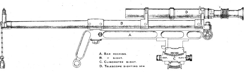
The rocking-bar pivoted at the front via an extension of the left-hand gun trunnion and connected at the rear to a rod driven by the gun’s elevating gear. The gun detachment No. 3 or gun layer sat to the left of the gun barrel and was responsible for using the sights to aim to gun. To align the rocking-bar sights on the target, he used two hand wheels. The rear one was used to transverse the gun by up to 4.5 degrees to either side – this pivoted the complete gun carriage about a pivot on the axle tree. The other hand wheel that was referred to as the lower elevation wheel was used to elevate both the rear of the rocking-bar sight and the gun cradle. This hand wheel was used to align the sights on to the target and the elevation given to the gun at the same time was intended to compensate for the difference in height between the gun and the target. The elevation angle set up is called the ‘angle of sight’
The gun detachment No. 2 sat to the right of the gun and was responsible for opening and closing the breech and for setting the range for the gun. He did this by using the upper elevation wheel on the right-hand side that elevated the gun between +16 and -5 degrees . When operated, the upper elevation wheel did not move the rocking-bar sight maintaining an independent line of sight to the target. The No. 2 was provided with a range indicator dial that was graduated in both degrees and yards out to 6,200 yds. The additional elevation angle set up for the gun was called the ‘tangent elevation’.
The rocking-bar sight was used in direct fire mode when the target was visible to the gun layer. However, during the Boer War, both sides in the conflict made limited use of indirect fire although the means for doing this were very primitive at the time. Indirect fire requires both the elevation and azimuth of the gun to be set without being able to see the target by the gun crew.
Dial Sights
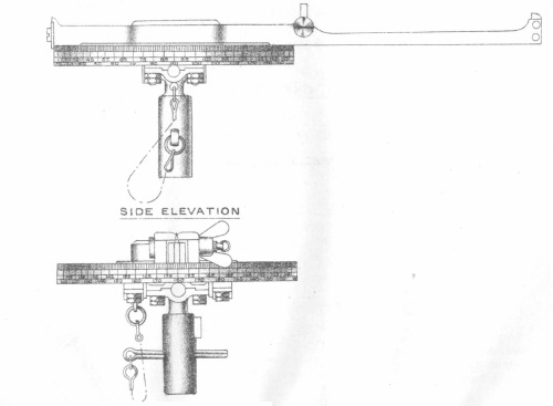
In the 13 Pdr, a clinometer was provided on the rocking-bar sights and used with the range dial to allow the elevation of the gun to be set in indirect fire mode. The problem of setting the azimuth direction for the gun in indirect fire mode was much more difficult. Originally a No. 1 dial sight was used mounted on the front of the shield as shown.
The No. 1 dial sight was provided with pivots to allow it to be levelled to compensate for the carriage wheels not being level. It was fitted with a turntable carrying an open set of sights with a bearing scale on the outside marked in degrees. In practice, the target direction was defined for the gun by an offset bearing relative to an aiming point that could be a natural future on the landscape or could be aiming posts specially set up some distance from the gun. To lay the gun for line, the offset target bearing was set up on the sight and then the gun traversed until the aiming point was aligned with the open sight.
The No. 1 dial sight was difficult to use except when the aiming point was in front of the gun. If the aiming point was behind the gun, the gun layer had to move round in front of the shield to use it which was not ideal. A much better solution came with the introduction of the No. 7 dial sight in 1910 that was based on the German Goertz periscopic panoramic sight. It was mounted on a bracket next to the rocking-bar sight.
The No. 7 dial sight consisted of a fixed eye piece at the bottom and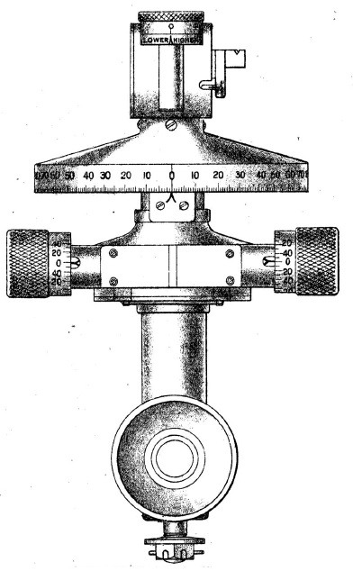 a sighting head at the top that could be rotated in azimuth by 180 degrees in either direction. It was fitted with an azimuth dial and micrometers to allow the azimuth angle for the sighting head to be set very accurately. Indirect fire was achieved by pointing the gun in azimuth by a pre-determined number of degrees offset from a reference direction that could be seen in the dial sight. The reference direction could be towards a known feature in the landscape or it could be achieved by using sighting posts some distance away placed in the ground. The advantage of the No. 7 dial sight was that the gun aimer could remain in his seat to look through the sight and then view the reference target in any azimuth direction but usually behind the gun.
One of the issues in aiming all rifled weapons is accounting for the spin drift of the projectiles. This is caused when the spin axis of the projectile starts to deviate from the direction of travel as the range increases. This, in turn, results in the drag force on the projectile producing a gyroscopic force that will move it in azimuth to the right when the spin is clockwise and to the left when the spin is counter-clockwise creating a drift in that direction. The 13-Pdr QF Gun imparted a right-hand spin to each shell causing a spin drift to the right. This was compensated for in the gun by tilting the axis of the trunnions down on the left-hand side by 1.5 degrees that then resulted in the muzzle moving to the left as the gun is elevated.
Gun Detachment Roles
The gun detachment consisted of 9 men of whom 6 worked at the battery and the remaining 3 formed a reserve. The duties of the detachment during WW1 were:
No. 1: Commanded the gun detachment positioned at the rear of the trail, responsible for re-positioning the spade on the end of the trail when more than 4.5 of traverse was needed.
No. 2: Sat to the right of the gun barrel and was responsible for opening and closing the breech and for setting the gun’s elevation and therefore its range – he was termed the ‘Range Setter’.
No. 3: Sat to the left of the gun barrel and was responsible for aiming the weapon and for firing it – he was termed the ‘Layer’.
No. 4: Stood to the left of the trail and was responsible for loading the next round into the breech – he was termed the ‘Loader’.
No. 5: Stood near the limber and was responsible for checking the fuzes and for handing the rounds to the No. 4 – he was termed a ‘Fuze Setter’.
No. 6: Stood near the limber and was responsible for extracting the next round from the limber and for setting the fuzes – he was termed a ‘Fuze Setter’.
However, later in WW1 when static artillery became the norm, it was usual for the use of the limber to be dispensed with in action and shells were stacked on the ground close to the gun requiring a smaller detachment to operate the weapon.
When travelling, No. 1 rode on horses stationed to the left of the front horse in the carriage limber. The Nos. 2, 3 & 4 rode on the left-hand carriage limber horses, the Nos. 5, 6 & 7 rode on the left-hand ammunition wagon limber horses and the Nos. 7, 8 & 9 sat on the ammunition wagon limber.
Ammunition
The 13-pdr fired fixed ammunition and shrapnel shells and star shells only. The cartridges were 12.3 inches long and the shells including fuzes were 9.5 inches long and weight 12 lb 8 oz. The Mk I shrapnel shell was fitted with a No. 80 time & percussion fuze that allowed a time delay of up to 22 seconds. When the fuze ignited, the flash travelled down the central brass tube to ignite the bursting charge in the base consisting of 1.25 oz of RFG. The shell was filled with 236 mixed metal balls fixed in resin. When the bursting charge ignited it forced the contents of the shell along with the fuze out of the front of the shell to spray the ground with shrapnel balls.
The star shells were filled with 10 stars. When the time fuze ignited, the per5forated central tube not only ignited the bursting charge in the base but also ignited the stars that were ejected out of the front of the shells to provide illumination as they fell to the ground.
13-Pdr QF 6 cwt
The 13-Pdr Mk I anti-aircraft gun was first approved in 1914 using a 13-pdr gun on a high angle mounting usually fixed to the back of a lorry. It was also known as the 13-pdr 6 cwt to distinguish it from the standard field gun where 6 cwt was the weight of the barrel and breech. The only change to the standard 13-pdr gun was the fitting of a catch to retain the shell when inserted at a high angle.
The Mk I mount had an additional recuperator mounted above the normal recoil housing to facilitate the gun’s run out at high elevation angles. The Mk II anti-aircraft mount included an improved recoil system that eliminated the need for the additional recuperator.
The main problem with the 13-Pdr 6 cwt was the poor ballistic performance of the shell that had the same muzzle velocity of just over 1600 fps as the field gun.
13-Pdr 9 cwt
The poor ballistic performance of the 13-pdr 6 cwt was overcome by utilising an 18-pdr gun barrel sleeved down to fire a 13-pdr shell using a necked down 18-pdr cartridge and charge. The resulting muzzle velocity was close to 2150 fps giving a maximum altitude of 19,000 feet. The new gun was referred to as the 13-pdr 9 cwt due to its heavier barrel.
The original Mk III anti-aircraft mount used was based on the Mk II used for the 13-Pdr 6 cwt but was not strong enough for the larger gun. The recoil stroke was therefore lengthened from 24 to 35 inches to relieve the strain on the mount. The Mk IV then became the standard anti-aircraft mounting on the Western Front for the remainder of WW1.
Given the time the shell took to reach even modest altitudes (10 s to reach 5,000 ft), sophisticated methods had to be developed to predict where the target would be by the time the shell reached it. Even then, it was rare for an enemy aircraft to be shot down and the main purpose of the anti-aircraft artillery was to put up barrages to deny the enemy aircraft with access over particular parts of the battlefield.
QF 13-Pdr Specifications
- Length: 11 ft 7 in
- Maximum Width: 6 ft 3 in
- Wheels: 4 ft 8 in
- Weight of Gun & Carriage: 19 cwt 8 lb
- Length of Gun Barrel: 5 ft 11 in
- Length of Bore: 73.26 in
- Bore: 3 in (76 mm)
- Weight of Gun & Breech: 6 cwt
- Muzzle Velocity: 1675 fps
- Maximum Range: 5900 yd
- Trail: Single pole
- Recoil System: hydro-spring (Mk I); hydro-pneumatic (Mk II)
- Maximum Recoil: 41 inch
- Rifling: Polygroove with modified plain section
- Length of Rifling: 55.8 in
- Twist: Right-hand twist with 1 turn in 30 calibres
- Grooves: 18
- Firing Method: Percussion
- Elevation: -5° to +16°
- Traverse: -4.5° left to +4.5° right
![]()