

During the 2nd Boer War (1899-1902), the main field gun in use by the British Army was the breech-loading BL 15-Pdr BL Gun that was introduced into service in 1892. It used the smokeless propellant Cordite and fired shrapnel shells to a maximum range of 6,000 yd. Although it was equipped with elementary devices to limit the recoil of the gun, it still needed to be re-laid before firing the next round which greatly limited the rate of fire.
However, these guns were outclassed by the Boer’s Creusot 75 mm QF guns, in particular, which incorporated a recoil system. In order to provide the army in South Africa with a more modern weapon, the War Office turned to Rheinische Metallwaaren- und Maschinenfabrik AG (now Rheinmetall AG) founded by Heinrich Erhardt in Germany for a quick solution. By this time, they had developed a field gun incorporating a modern hydro-spring recoil system. To avoid sensitivity in Germany over the Boer War, a secret order had to be placed with the company in 1900 for 108 of these 15-pdr guns to be used in South Africa, together with limbers and 54,000 rounds of ammunition. The gun was designated the 15-Pdr QF Gun in British service although it was often referred to as the Erhardt .
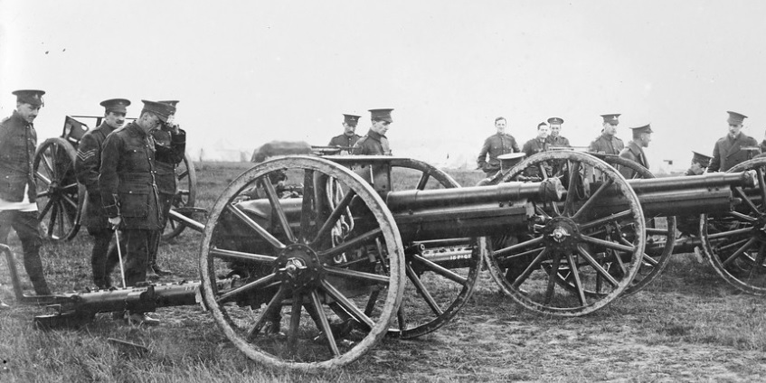
The Royal Horse Artillery (RHA) and Royal Field Artillery (RFA) were re-equipped with the new 13-Pdr QF and 18-Pdr QF guns, respectively, beginning in 1904. However, when the Territorial Force was set up in 1908, the Erhardt guns were assigned to the territorial batteries of the RHA in modified Mk I* form. These served with some of these units in the early part of WW1 until finally replaced in 1916 by the new 13-pdrs.
Carriage
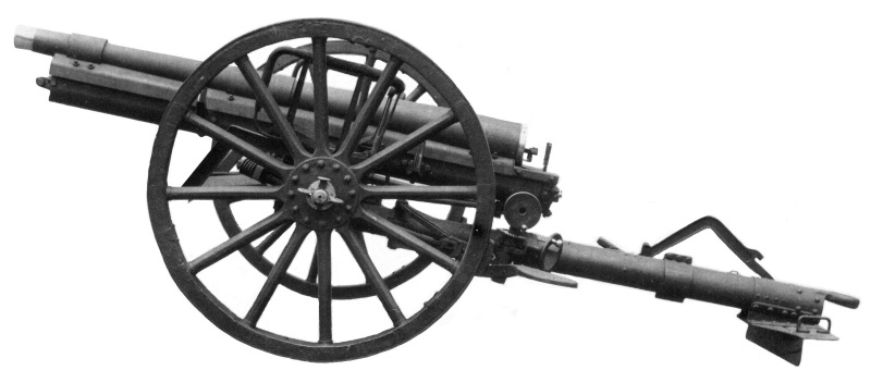
The 15-pdr was mounted on a carriage with a tubular steel trail that allowed for a maximum elevation of the gun of 16 degrees with up to 5 degrees of depression. The trail was equipped with a spade and folding traversing pole at the rear and was equipped with standard wooden wheels at the front.

The wheels were fitted with brake arms at the rear applied using hand wheels at the front and rear. They were fitted with cast iron brake shoes that acted against the steel tyres on the wheels. In line with normal German practice, axle seats were provided for two of the gun crew during towing of the gun which was facilitated by a towing eye on the rear of the trail. The gun was towed via a two wheel limber pulled by 6 horses.
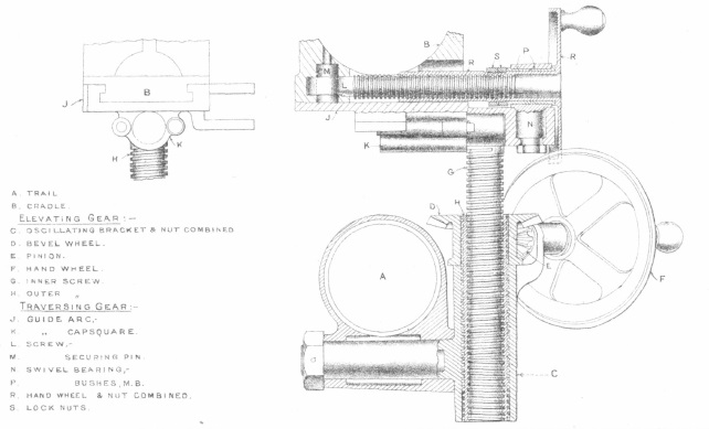
 The gun recoiled within a steel cradle of U-shaped cross-section that was equipped with a vertical pivot that fitted into a socket on the axle tree providing up to 3 degrees of traverse of the gun to the left or right. The combined elevating and traversing mechanism was attached to the trail just under the breech with a screw jack operated by the lower hand wheel used to elevate the gun. Above this, another hand wheel operated a horizontal screw jack connected to the cradle allowing the gun to be traversed.
15-Pdr QF Gun Mk I*
For use by the Territorial Force after 1908, a number of modifications were made to the original carriage changing its designation to 15-Pdr QF Gun Mk I*. The main changes included the removal of the axletree seats and the fitting of a splinter shield whose top and bottom parts could be lowered to facilitate towing. The other change was to fit improved sights including a dial sight to facilitate indirect fire.
Gun Design
The gun was made of nickel steel and consisted of a rifled A-tube with a jacket shrunk over the rear half and secured by a screwed steel ring. The jacket was extended at the rear to receive the breech block. Two steel guide rings were shrunk on to the A-tube, one in front of the jacket securing ring and the other near the muzzle secured by another screwed steel ring. The front guide ring was fitted underneath by a lug to which the front of the hydraulic recoil buffer cylinder was attached. Enclosed guide rails were attached to the two guide rings and also attached to the jacket to support the gun on the cradle as it recoiled. A plane for a clinometer was provided on top of the breech and vertical and horizontal lines were cut on the breech and muzzle faces.

The gun was fitted with a single motion breech mechanism such that, when the lever was pulled, this rotated and unlocked the breech and then swung the breech block and carrier to the right to the loading position. The breech was closed by a steel taper breech block provided on the exterior with annular collars having five interruptions, each one-tenth of the circumference. The interior of the breech had corresponding annular collars and, after being pushed home, was locked by a tenth of a turn. On opening the breech, the extractor automatically ejected any cartridge in the breech.

The breech was designed for percussion firing using a firing pin that was cocked when the breech was opened. The gun was fired using a lanyard attached to the firing wedge that released the striker.
Recoil System
The 15-Pdr QF Gun used a hydro-spring recoil system mounted within the gun cradle. This consisted of an oil filled hydraulic buffer to absorb the recoil energy and a recuperator spring to return the gun back to battery.
The hydraulic cylinder was screwed into the front guide ring of the gun and therefore recoiled with the gun. Within the cylinder, the piston was fitted on a rod that passed through a gland in the front of the cylinder and was held in position attached to the front of the cradle. When the gun recoiled, oil was forced to flow past the piston via grooves in the surface of the cylinder absorbing the recoil energy as it did so. The grooves were of varying width in order to regulate the flow of oil. The nominal length of recoil was 48 inches.
Around the outside of the hydraulic cylinder were 8 spiral springs separated by parting plates. As the gun recoiled, these springs were compressed by the moving hydraulic cylinder against the rear of the cradle. When the recoil came to a stop, the springs then returned the gun to battery. In order for the gun to be brought to a gentle stop, the rear extension of the piston rod entered a narrow oil filled buffer towards the end of the movement. 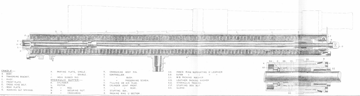
Sights
The Mk I gun was sighted on the left-hand side of the cradle with fore and hind sights. The foresight consisted of a pointed steel pillar fitted to a bracket on the cradle and secured by means of a taper bolt and nut. The hindsight consisted of a curved sight bar (U-section) provided with a cross head having a notched deflection leaf and traversing screw (giving 2 degrees deflection right and left), and having a sight socket that was fitted to a bracket on the cradle by means of a taper bolt and nut.
The sight bar was graduated on the rear face with a yard scale and on the side face with a degree scale. The front face of the bar was provided with a rack engaging with the pinion in the sight socket and was fitted with a drum graduated up to 6,400 yards. An adjustable level was fitted to the sight bar immediately below the cross head that was provided with a rack gearing and pinion and milled knob on the sight bar graduated in degrees. The level could be used as a clinometer.
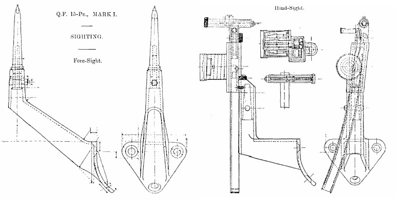
In practice, the required range was set on the sight and then the gun elevated until the sight bubble was levelled. The sights could be used in both direct fire and indirect fire with the latter carried out with the aid of sighting posts and the deflection scale. In indirect mode, the gun was roughly aligned in the estimated target direction and then the aiming posts set up in front of the gun in that direction. The deflection scale was then used to apply deflection corrections with the sight aligned with the aiming posts each time.
Mk I* Sights
The Mk I* was fitted with a rocking bar sight attached to the cradle via front and rear brackets that allowed for the fitting of a x5 power No. 6 sighting telescope to supplement the open sights.
The new sights were also reciprocating in order to compensate for the effect of the carriage wheels and, therefore the gun trunnions, not being level as was the norm. This tilting led to the vertical plane containing the gun being rotated away from the centreline of the carriage in the direction of the lowest wheel. If this was not compensated for, it resulted in a large sighting error especially at higher elevation angles. The effect was compensated for simply by tilting the sights about an axis parallel to the gun to put them back into the vertical plane.
In the bar sight, the tilting was achieved by using a ball joint on the front cradle bracket and using a reciprocating bracket on which the sights were mounted that was hinged to the rear cradle bracket. The tilting was carried out using the traverse adjustment knob and the cross-level provided. The cross-level was actually set at an angle of 1° 30′ in order to compensate for the spin drift of the projectiles.
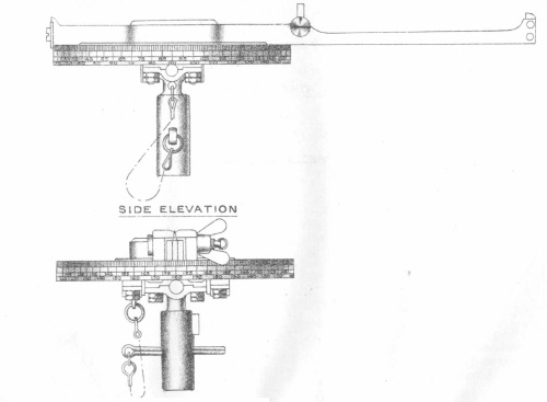
The bar sight was mounted on the reciprocating bracket via a toothed arc that could be raised or lowered using the hand wheel provided that also rotated a range drum graduated in 25 yd steps up to a maximum range of 6,400 yd. The upper end of the toothed arc was fitted with a deflection screw working within a T-shaped crosshead on the upper face of which the sight bar travelled. A deflection scale plate was fitted to the rear face to indicate up to 2 1/4 degree deflection right and left. The rear of the sight bar was provided with bracket for the x 5 power No. 6 sighting telescope.
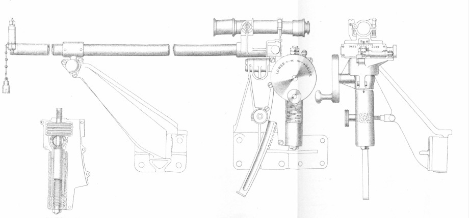
Indirect fire was provided for using a No. 1 dial sight fitted with a socket that fitted on to a pillar on the front bracket supporting the rocking bar sight. The dial sight was provided with pivots to allow it to be levelled to compensate for the gun being elevated and for the carriage wheels not being level. It was fitted with a turntable carrying an open set of sights with a bearing scale on the outside marked in degrees. In practice, the target direction was defined for the gun by an offset bearing relative to an aiming point that could be a natural future on the landscape or could be aiming posts specially set up some distance from the gun. To lay the gun for line, the offset target bearing was set up on the sight and then the gun traversed until the aiming point was aligned with the open sight.
Compared with the Ordnance 18-Pdr QF Gun, the sights on the Mk I* 15-Pdr were a little basic. They were not fitted with an adjustable clinometer and so the angle of sight could not be independently set on the sight which meant that the elevation of the target could not be easily taken into account when setting the range. By the time that the Territorial Force had been set up in 1908, both the 13-Pdr and 18-Pdr were using a No. 7 dial sight employing a panoramic telescope allowing laying for line in indirect fire mode much easier for the gun layer. The 15-Pdr was not modified to accept the No. 7 dial sight and went to war in 1914 with the No. 1 dial sight.
Ammunition
The 15-Pdr QF Gun used separately loaded shells and cartridges. 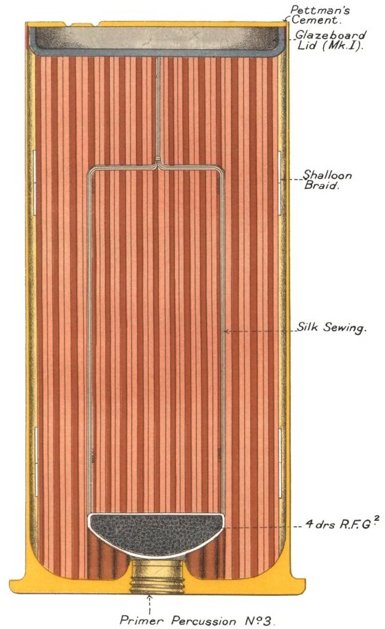 The cartridges consisted of brass cases filled with MDT Cordite and enclosed at the top with a glazed board. The Mk I cartridge was fitted with a cap in the base for igniting the charge and used an igniter in the bottom of the cartridge consisting of 2 drams of guncotton yarn. The MK II cartridge used a primer instead of a cap that screwed into the base and used 4 drams of SFG powder distributed at the bottom of the case. The Mk III cartridge was similar to the Mk II but used 4 drams of RFG power in a cup above the primer to act as an igniter.
The 15-Pdr fired 3 types of shell: Shrapnel, shot or case, and star. The Shrapnel shells were filled with 230 balls fixed in resin and were detonated using N0. 60, 60c or 63 time and percussion fuzes. When the fuze ignited, it sent a flash down the central tube within the shell that detonated the bursting charge. This charge blew off the top of the shell and sprayed the Shrapnel balls out ahead of the shell at high speed like a shot gun cartridge. The case shot was filled with 290 balls that were forced out of the front of the shell when the cartridge was fired.
The star shell was similar in operation to a Shrapnel shell but the central flash tube included holes which allowed the flash to ignite the 10 x incendiary stars before the bursting charge propelled them out of the front of the shell.
The 15-Pdr used No. 58, No. 60 and No 63c time and percussion fuzes with a maximum time delay of 20 s. These were eventually replaced by the No. 63 fuze shown below.
15-Pdr QF Gun Specifications
- Length: 14 ft 5 in
- Maximum Width: 6 ft 2 in
- Wheels: 4 ft 6 in
- Weight of Gun & Carriage: 20 cwt 32 lb
- Length of Gun Barrel: 90 in
- Length of Bore: 85.79 in
- Bore: 3.0 in (76 mm)
- Weight of Gun & Breech: 6 cwt 65 lb
- Muzzle Velocity: 1674 fps
- Maximum Range: 6400 yd
- Trail: Single pole
- Recoil System: hydro-spring
- Maximum Recoil: 48 inch
- Rifling: Polygroove with modified plain section
- Length of Rifling: 77.403 in
- Twist: RH increasing from 1 turn in 60 calibres to 1 turn in 25 calibres
- Grooves: 28
- Firing Method: Percussion
- Elevation: -5° to +16°
- Traverse: -3.0° left to +3.0° right
![]()