

The 6-Inch BL 30 cwt Howitzer was introduced in 1896 and was the only equipment available for the siege batteries of the Royal Garrison Artillery when it went to war in 1914. However, in common with the 4.7-Inch BL Heavy Field Gun adopted after the 2nd Boer War (1899-1902), it was equipped with a recoil system that was split between the gun and carriage and was less than satisfactory. The maximum range of the howitzer was also relatively short at about 7,000 yds.
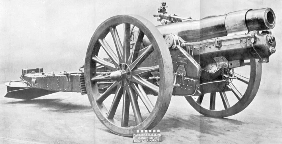
Work began on a replacement in 1915 to be equipped with a sophisticated hydro-pneumatic recoil system and a box trail. The maximum range of the new howitzer was 9,500 yds eventually extended with a lighter shell to 11,400 yds. It was designed by Vickers and designated the BL 6-Inch 26-cwt Howitzer with the 26 cwt indicating the weight of the gun and breech to distinguish it from the earlier howitzer. It remained in service until 1945.
Mk I Gun
The gun consisted of a rifled A-tube, muzzle stop ring, layers of steel wire, jacket, guide ring, breech ring and breech bush. The stop ring was shrunk on to the muzzle and then the layers of steel wire wound along the remaining length of the A-tube. The jacket was then shrunk over the wire layers and the stop ring. The breech bush was screwed into the end of the jacket and the breech ring was screwed over the end of the jacket and included lugs for attachment of the hydraulic buffer and recuperator. The guide ring was shrunk on to the jacket near the muzzle and along with the jacket included horizontal ribs that slid in guides in the cradle when the gun recoiled.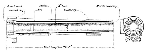
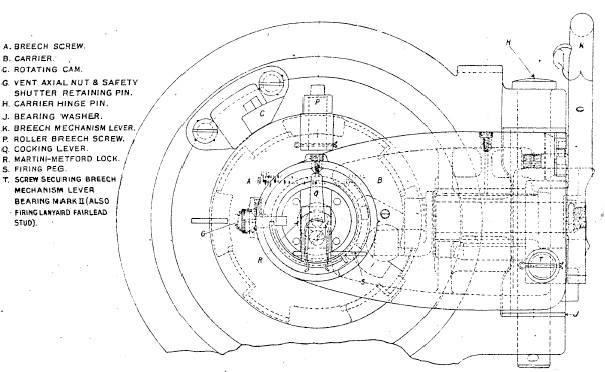
A single motion breech was fitted that required a single pull on the lever on the right to unlock the breech and to swing it out of the way allowing the next round to be loaded. The breech screw was of the parallel Welin type. Obturation or breech sealing was achieved using a mushroom shaped axial vent with seal behind it that was pressed against the coned rear of chamber when the breech was closed. When the gun was fired, the pressure in the chamber pushed back on the axial vent further pressing the seal against the side of the chamber. The cartridge was fired using a ‘Tube, Percussion, S.A. Cartridge’ inserted into the back of the axial vent and triggered using a percussion lock and lanyard.
Recoil Mechanism
The recoil mechanism was contained in a cylinder block attached at the rear to the breech ring via connecting studs and recoiled along guides in the gun cradle. Four cylinders were contained in the cylinder block with the upper one forming the hydraulic buffer and the lower one the recuperator. Each one was fitted with a piston fixed to the front of the cradle via a piston rod. Either side of these two cylinders were high pressure (HP) cylinders with a floating piston separating the oil at the front from compressed air at the back.
As the gun recoiled and the oil filled hydraulic cylinder was pulled backwards, the oil had to flow through the piston resisting its movement and absorbing the energy of recoil. The piston was fitted with ports for this purpose but was also fitted with a rotating valve with similar ports. The rotating valve was keyed into a pair of spiral grooves in the surface of the hydraulic cylinder that caused it to rotate when the gun recoiled. At the start of recoil both sets of ports were aligned to provide maximum oil flow rate but, as the gun recoiled and the rotating valve rotated, a point was reached where the sets of ports were no longer aligned and the flow of oil was therefore stopped thus bringing the recoil to an end.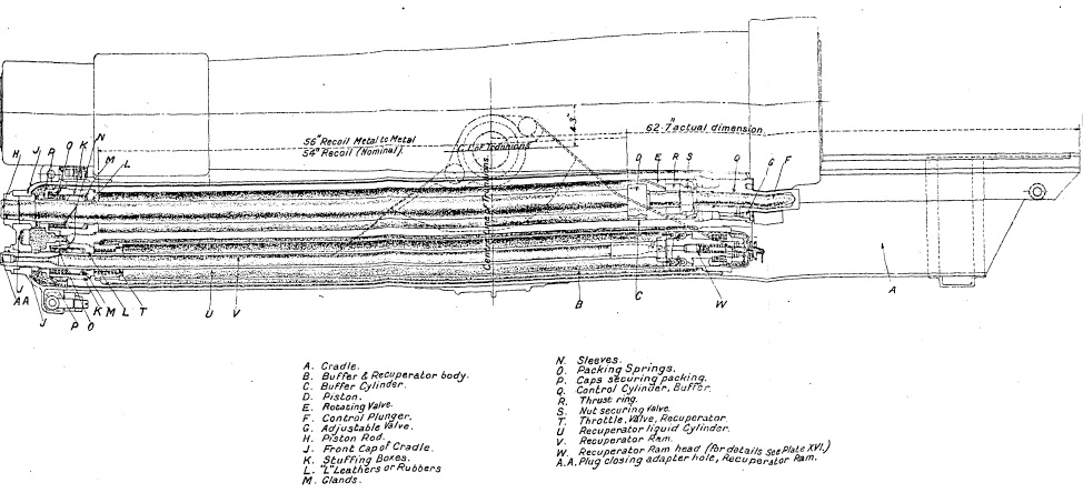
The recuperator cylinder contained oil in front of the piston. When the gun recoiled, this oil was forced into the front of the two HP cylinders pushing the floating pistons backwards in the cylinders and compressing the air . Once the recoil had been stopped, the compressed air then forced the oil back into the recuperator cylinder running out the gun. The nominal air pressure in the HP cylinders was maintained at about 700 psi to keep the gun in position when it was elevated.
The rear end of the hydraulic piston was formed into a control rod that entered a control chamber filled with oil towards the end of run out. By having to displace this oil, this effectively brought the run out to a controlled stop. The gun was also fitted with a cut-off gear. This was connected via an actuating rod on the right-hand side of the gun to a link that rotated on the gun trunnion and a gear at the front of the cradle that rotated the hydraulic piston rod. This rotation of the piston rod changed the point at which the rotating valve cut off the flow of oil to bring the recoil to an end. At 0 degrees elevation, the length of recoil was 52 inches but, at 45 degree elevation, it was reduced to 24 inches to avoid the breech hitting the ground.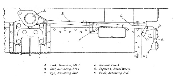
Mk I Carriage
The carriage was designed to allow the howitzer to be fired at elevation angles from 0 degrees to 45 degrees. The gun recoiled in the cradle that was fitted with trunnions to allow it to pivot on the saddle. The saddle consisted of two side pieces connected by a curved transom at the front and pivoted on the front of the trail to provide up to 4 degrees of traverse to the left of the right.
The trail consisted of two steel side brackets connected at the front by a transom on which the saddle pivoted and at the rear by a top and bottom plate. The trail was fitted at the rear with a spade and a towing eye. The axle tree fitted to the trail mounted two 5 foot diameter wooden wheels with 6 inch wide steel tyres. Brake shoes were fitted behind each wheel that pivoted via swinging arms from the trail and were applied using hand wheels. However, when girdles were fitted to the wheels, the brake shoes had to be removed first and stowed on the trail. 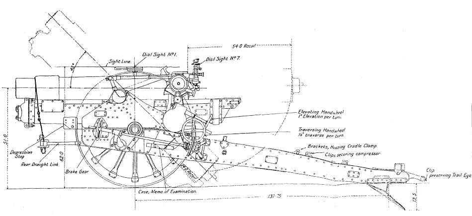
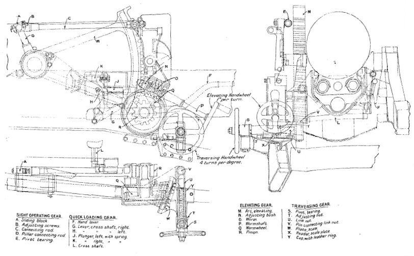
The gun was traversed using a hand wheel on the left at the back of the saddle. The gun was elevated via a hand wheel on the left just behind the traversing hand wheel and engaged with an elevating arc that pivoted about the left gun trunnion. In normal use, a plunger was used to engage with a recess in the elevating arc to lock it to the gun cradle to allow the gun to be elevated. However, a quick loading lever was provided on the right of the gun that, when raised, withdrew the locking plunger from the elevating arc allowing the gun to lowered to an elevation of 7.5 degrees for loading the next shell. Once loaded, the quick-loading lever was lowered raising the gun and locking it back into the elevating arc.
The gun was normally towed behind its two wheeled limber that was used to store tools and spares for the howitzer. The gun and limber were designed to be towed by horses but, later in WW1, mechanised towing was normally used. During transport, the cradle was clamped at the rear to the trail to avoid damage to the elevating and traversing gears. In the 1930’s with the switch to mechanised towing, the original wheels were replaced by smaller wheels with pneumatic tyres. In this form, it served the British Army until 1945 although largely replaced after 1942 by the BL 5.5-Inch Medium Gun.
Gun Sights
The sights were supported on a sight bracket that pivoted on the saddle some distance behind the left-hand gun trunnion to place them in a more convenient position to use. The sight bracket was rotated through the same angle as the gun via a parallel motion link with its operating arm pivoting with the end of the elevating arc on the gun trunnion.
The sights were oscillating or reciprocating to compensate for the carriage wheels not being level. This was normally the case and resulted in the vertical plane containing the gun being rotated in azimuth in the direction of the lower wheel – the greater the elevation angle, the greater was the rotation angle. To compensate for this effect, the sights were mounted on an oscillating bracket that pivoted on the sight bracket about an axis parallel to the gun. In practice, the oscillating plate was aligned with the vertical plane using the cross level bubble and adjustment screw ensuring the sights were then in the same plane as the gun therefore compensating for any tilt of the wheels.
The oscillating bracket contained a cover on the outside for the toothed range quadrant to which the sights were mounted. The range quadrant was rotated using the small hand wheel provided that also turned the range dial that was graduated from 0 – 45 degrees. The range quadrant supported a bracket for the sight clinometer and the tubular sight bar, or rocking bar. This had a fixed acorn fore sight and a notched back sight mounted on a bracket providing deflection from 5 degrees left to 5 degrees right.
The sight clinometer could be set to provide up to 20 degrees of elevation or 20 degrees of depression. It was used to set the angle of sight which was the difference in elevation angle between the target and the horizontal plane through the gun. In indirect fire mode, the required range was converted to a tangent elevation angle using range tables. To lay the gun, the required angle of sight was set on the clinometer and the required tangent elevation set on the range dial. The gun was then elevated until the clinometer bubble was level indicating that the required quadrant elevation angle (the sum of the angle of sight and the tangent elevation) had been set.
The carrier for the No. 7 dial sight was also fixed to the range quadrant. This carrier also included the means for providing up to 10 degrees of deflection to the left or right. The required azimuth bearing for the gun was determined by a plotting officer using a map and defined as an offset angle from the gun’s aiming point. The aiming point was a clearly defined feature in the landscape which could be behind or in front of the gun. The required offset was set on the panoramic dial sight and the gun then traversed until the aiming point was centred in the sight at which point the gun had the correct target bearing.
In addition to providing a deflection adjustment, the oscillating bracket was given a fixed tilt of a few degrees to the left when the cross bubble was leveled in order to account for the drift of the shells to the right.
Ammunition
The 6-inch howitzer fired high explosive (HE), incendiary, smoke, gas and star shells, all weighing 100 lb. It used separate bagged cartridges that included igniter patches sewn into the base.
The HE shell weighed 100 lb and was fitted with a No. 101 percussion fuze or No. 106 direct action percussion fuze. It had a 2 calibre radius head. A common pointed shell was also used which had a solid nose with the No. 16 percussion fuze mounted in the base. After WW1, an 86 lb streamlined HE shell was developed with a 9.25 calibre radius head that increased the maximum range to 11,400 yds.
The shrapnel shell was filled with lead/antimony balls and fitted with a No. 82 time & percussion fuze. The fuze could be set to provide a time delay of up to 22 time units by rotating a time ring. When fired, the time pellet in the nose of the fuze was driven against a needle setting it off that, in turn, ignited a gunpowder trail whose length was determined by the time delay setting. When this burned through, it ignited the powder in the base of the fuze that then ignited the powder in a central tube connecting it to a bursting charge in the base of the shell. When this ignited, it blew off the fuze and propelled the shrapnel balls at high speed out of the front of the shell spraying the ground ahead of the shell. The fuze was also fitted with a percussion pellet that detonated the shell if it hit the ground before the time fuze burned through.
The gas shell was similar to the HE shell and included a percussion fuze and bursting charge in the nose. The start shell was of the parachute type and was fitted with a No. 183 time fuze and bursting charge that ejected the contents out of the base of the shell. The smoke shell was also base ejecting and contained phosphorus pellets that generated dense smoke that ignited on exposure to air on the ground.
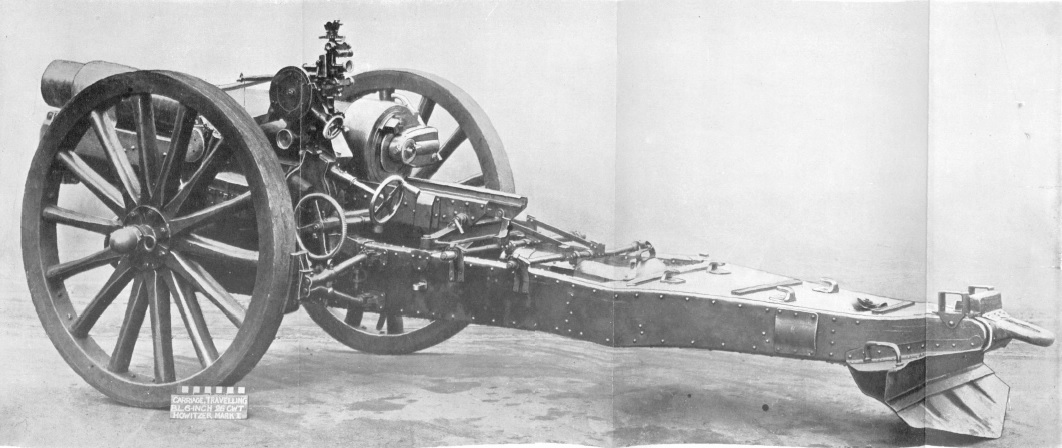
BL 6-Inch 26 CWT Howitzer on Travelling Carriage Specifications
- Length: 17 ft 6 inch
- Maximum Width: 7 ft 10 inch
- Wheels: 5 ft in diameter
- Weight of Gun & Carriage: 72 cwt 78 lb
- Length of Gun Barrel: 7 ft 3.5 inch
- Length of Bore: 6 ft 8 inch
- Bore: 6 inch
- Weight of Gun & Breech: 25 cwt 56 lb
- Muzzle Velocity: 1400 fps
- Maximum Range: 9,500 yd with 100 lb shell; 10,400 yd with 86 lb shell
- Trail: Box
- Recoil System: hydro-pneumatic
- Maximum Recoil: 52 inch at 0° elevation and 24 inch at 45° elevation
- Rifling: Polygroove with modified plain section
- Length of Rifling: 5 ft 5.5 inch
- Twist: Right-hand 1 turn in 15 calibres
- Grooves: 36
- Firing Method: Percussion
- Elevation: 0° to +45°
- Traverse: -4° left to +4° right
![]()