

During the 2nd Boer War (1899-1902), 4.7 inch guns from HMS Terrible were mounted on improvised wooden carriages by Captain Percy Scott to provide the Army with a small number of long range field gun to counter the ‘Long Tom’ guns used by the Boers. Later on, two 6 inch Mk I or II guns from HMS Terrible were also used in a similar way.
Pre-WW1, 45 calibre 6 inch Mk VII naval guns were used on garrison carriages for coastal defence. In 1915, the decision was taken to mount some of the Mk VII guns on improvised travelling carriages in order to provide the Army with a long range gun for counter-battery work. These guns were designated the 6-Inch BL Gun Mk VII and were improved in 1917 with the Mk II carriage providing a greater elevation angle with an increase in maximum range to 13,700 yds. However, these guns incorporated the short hydro-spring recoil system from their original garrison mountings requiring the use of curved ramps or scotches behind the wheels in field use to help return the gun to battery. The guns were also very heavy at about 25 tons presenting considerable problems in emplacing them even with mechanised towing. Despite these shortcomings, the guns proved to be effective during WW1 and continued to be used post-WW2 as coastal defence guns.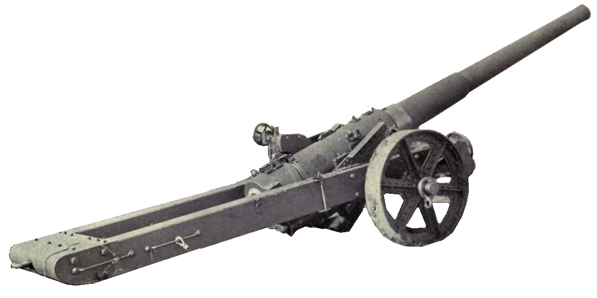
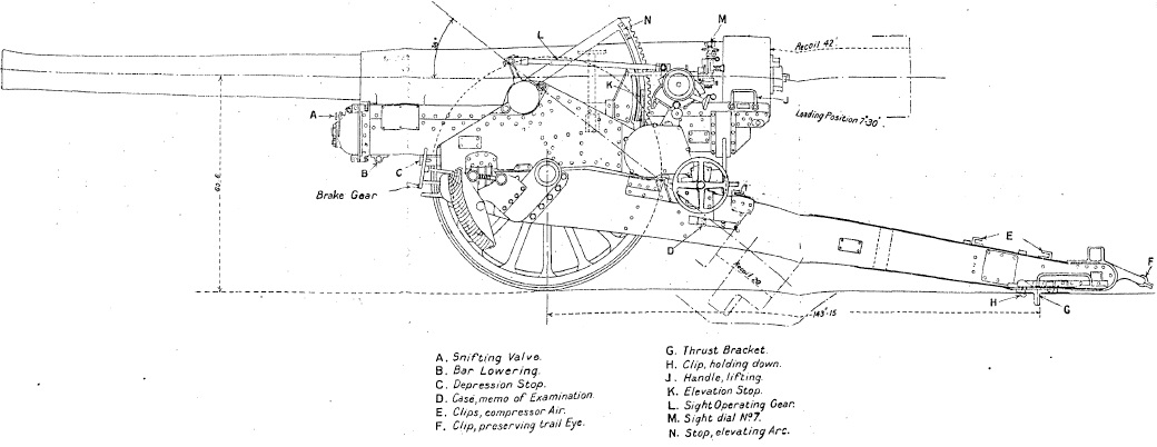
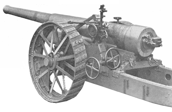
However, a lighter replacement was requested in 1916 and this was achieved by Vickers by redesigning the original gun and reducing its length to 35 calibres. In this form, shown below, it was designated the BL 6-Inch Mk XIX Gun. The Mk XIX gun was mounted on the carriage of the BL 8-Inch Howitzer Mk VII giving it an elevation of up to 38° and a maximum range of 18,750 yds. It served throughout the remainder of WW1 but was effectively superceded early in WW2 by the US 155 mm Gun M1 with the carriages then re-used for the BL 7.2-Inch Howitzer.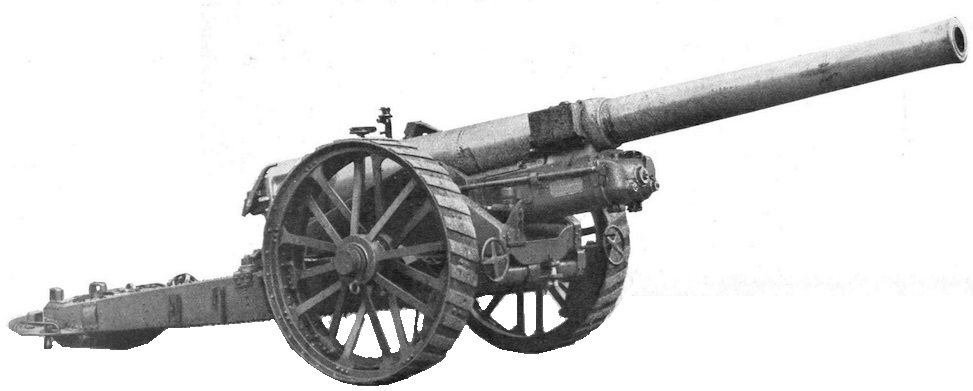
Gun Design
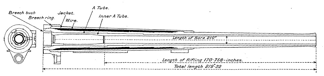
The Mk XIX gun was made from steel and consisted of a rifled A-tube with an inner A-tube extending from the seat of the obturator to the muzzle. The inner A-tube was retained in position by a shoulder and by the breech bush that screwed into the rear of the A-tube. Extending over the chamber and also almost half the length of the gun were wound successive layers of steel wire. The jacket was then shrunk on to the wire and part of the A-tube at the front and retained in position by a shoulder and the breech ring at the rear that screwed on to it. The breech ring provided a lug underneath to attach it to the recoil system and a lug on the right-hand side for the breech carrier pivot.
Projections were formed on the underside of the jacket at the front and rear with gunmetal bearing strips that allowed the gun to slide on the cradle during recoil. An oil filled gravity tank was fixed to the right-hand side of the jacket that provided lubrication of the bearing strips.
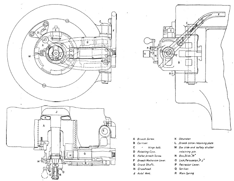
The breech was a Asbury single motion type with Welin type breech screw. The breech was operated by a lever on the right. When pulled backwards, this unlocked the breech screw and then swung it clear to the right to allow the next round to be loaded. The breech screw was fitted with a mushroom headed axial vent that incorporated an obturator pad behind the mushroom for use with bagged cartridges. When the breech was closed, the obturator pad was forced against the coned rear of the breech. When the loaded cartridge was fired, the chamber pressure pushed the axial vent backwards which, in turn, pushed the obturator pad hard against the sides of the chamber fully sealing it. The cartridge was fired using a percussion lock and ‘Tube, Vent-Sealing Percussion’ inserted into the back of the axial vent. The cartridges included igniter pads of gunpowder sewn into pockets at the rear that were ignited by the flash from the percussion cartridge traveling down the hole in the axial vent.
Recoil Mechanism
The recoil mechanism consisted of a hydraulic buffer to absorb the recoil forces and a hydro-pneumatic recuperator to return the gun to battery. The recoil system was contained in a cylinder block that was connected to a lug under the breech ring and recoiled with the gun in the cradle. There were 5 cylinders in the cylinder block: the centre one formed the hydraulic buffer; the two lower ones on either side formed the liquid (oil) cylinders for the recuperator; and the two upper ones on either side formed the high pressure (HP) air cylinders for the recuperator.
The hydraulic cylinder was filled with oil and contained a piston on the end of a rod fixed to the front of the cradle. As the gun recoiled and the hydraulic cylinder was pulled backwards, the oil in front of the piston had to flow through small ports in the piston restricting its flow rate and therefore absorbing some of the recoil energy. Immediately behind the piston was a rotating valve that had similar ports to those in the piston. The rotating valve was keyed to a pair of spiral grooves on the inside surface of the buffer cylinder that caused it to rotate when the gun recoils. At the start of the recoil, the two sets of ports were aligned to produce maximum oil flow rate through the piston but, as the rotating valve rotated, a point was reached where the flow of oil was cut off and the recoil was ended.
The Mk XIX gun was fitted with a cut-off gear to limit the length of recoil at the higher elevation angles. The mechanism was operated by a control rod that pivoted on the cradle near the right trunnion and was connected to an actuating arm on the end of a cross-spindle at the front of the cradle. As the gun elevated, the control rod pulled the actuating arm backwards which then rotated the hydraulic piston rod via bevel gears on the cross-spindle shortening the length of recoil. The recoil varied from 42 inches when the gun was horizontal reducing to 20 inches when the gun was elevated to 38°. However, it still required a shallow pit to be dug out under the breech to stop it hitting the ground at the higher elevation angles.
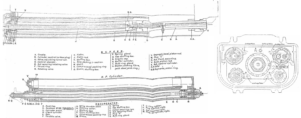
The gun used two pairs of liquid and high pressure cylinders on either side of the cylinder block that were interconnected by passages to equalise the pressures generated. The liquid cylinders were connected to the cylinder block at the rear but were surrounded by an annular space filled with oil that was connected to the rear of the corresponding HP cylinder. The cylinders were referred to as being rams. Inside the rams was a piston connected via a rod to the front of the cradle such that, when the gun recoiled, the piston remained stationary and the rams moved backwards with the gun. As the gun recoiled, the piston forced the oil in front of it into the annular space around the rams and then into the rear of the HP cylinders compressing the air there.
On the front of the rams was a throttle valve that opened during recoil to allow the free passage of oil. After the recoil had been brought to a stop, the compressed air in the HP cylinder then forced the oil back into the rams at the same time returning the gun to battery. While this was happening the throttle valves closed and the oil then had to pass through small holes in them controlling how fast the gun moved. The end of the hydraulic buffer rod behind the piston was also formed into a control rod that entered a narrow cylinder filled with oil as the gun returned to battery helping to bring it to a gentle stop. The HP cylinders were normally pressurised at 740 psi to keep the gun run out when it was elevated.
Mk VIII & VIIIA Carriages
The Mk VIII carriage for the 6 inch gun was derived from the BL 8-Inch Howitzer Mk VII carriage with changes made to allow the 6 inch gun to be fired at elevation angles of up to to 38°. The Mk IIIA carriage was similar to the Mk VIII carriage but with slight changes to the recoil system (principally a larger diameter buffer cylinder) and the cradle end cap.
The gun recoiled in the cradle that was fitted with trunnions to allow it to pivot on the saddle. The saddle consisted of two side pieces connected by a curved transom at the front and pivoted on the front of the trail to provide up to 4° of traverse to the left of the right. A traversing hand wheel was provided on the left-hand side of the trail.
The trail consisted of two side box section brackets joined at the front by a transom and at the rear by a top and bottom plate. The transom included a bearings for the saddle pivot. A detachable spade was fitted to the rear of the trail which also included a towing eye. A draught link was fitted to the centre of the front transom to allow it to be connected to another limber or the carriage for the firing platform.
Brackets were fitted to the front of the trail for the axle tree that was fitted with traction engine steel wheels 5 ft 6 inches in diameter and 12 inches wide. Brakes shoes acted against the inside front of each each wheel operated independently by hand wheels on either side in front of the carriage.
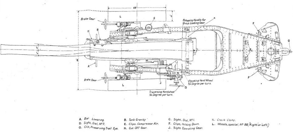
The gun was elevated via a hand wheel on the left. The hand wheel rotated a horizontal shaft with a bevel gear on the end that ultimately rotated a pinion via a gear train that meshed with the elevating arc attached to the cradle on the left. The gun was traversed using the traversing hand wheel that rotated a traversing screw via a set of spur gears. The nut on the screw was attached to the cradle traversing it sideways by up to 4 in either direction.
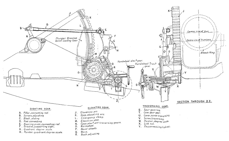
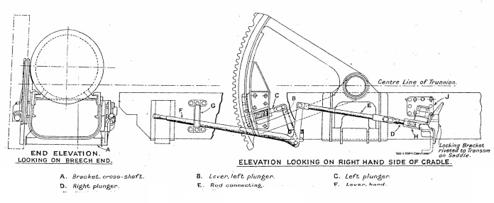
The howitzer was fitted with a quick-loading gear that enabled to the gun to be quickly lowered to enable the next round to be loaded. This consisted of a hand lever on the right of the carriage which, when raised, disengaged the cradle from the elevating arc by withdrawing a cross-spindle. When disengaged, the lever then allowed the gun to be quickly depressed to 7.5° elevation for loading at which point it was locked in position by the cross-spindle. Lowering the lever then unlocked the gun and allowed it to be raised again and locked back into the elevating arc. When the quick-loading gear was used, the sights were not disturbed.
 Firing Platform
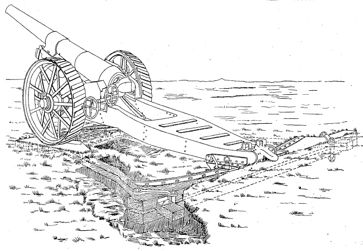
The gun was normally fired using the spade on the back of the trail to stop it from recoiling backwards. However, it was also designed to be mounted on a firing platform as shown below that required the spade to be removed first. A curved steel track was fitted to the cross beams with holes spaced at 4° intervals to which the trail was locked via a pin. Using the angle brackets on either side of the trail allowed the gun to be traversed in 2° steps.
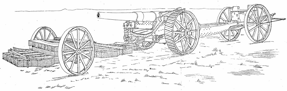
Transport
Mechanised towing was normally used to transport the gun behind its two wheeled limber used for carrying spares and tools. The firing platform was moved by re-positioning the wooden beams and then attaching an axle tree and wheels to allow it to be towed behind the gun. Originally, the 6 inch howitzer had been designed using metal traction engine wheels. However, with the adoption of higher speed mechanised transport, the original carriage was modified in the 1930’s to use 40 inch wheels with 14 inch pneumatic tyres.
Gun Sights
The sights were similar to those on the BL 8-Inch Howitzer. They were supported on a sight bracket that pivoted on the saddle some distance behind the left-hand gun trunnion to place them in a more convenient position to use. The sight bracket was rotated through the same angle as the gun via a parallel motion link with its operating arm pivoting on the left-hand gun trunnion.
The sights were oscillating or reciprocating to compensate for the carriage wheels not being level. This was normally the case and resulted in the vertical plane containing the gun being rotated in azimuth in the direction of the lower wheel – the greater the elevation angle, the greater was the rotation angle. To compensate for this effect, the sights were mounted on an oscillating bracket that pivoted on the sight bracket about an axis parallel to the gun. In practice, the oscillating plate was aligned with the vertical plane using the cross level bubble and adjustment screw ensuring the sights were then in a vertical plane parallel to that of the gun therefore compensating for any tilt of the wheels. However, in order to compensate for drift, the sights were inclined at an angle of 3° to the left and given a permanent deflection of 10′ to the right.
The oscillating bracket contained a cover on the outside for the toothed range quadrant to which the sights were mounted. The range quadrant was rotated using the small hand wheel provided that also turned the range dial. The degree scale plate was engraved from 0° to 38° and was read by a reader bar that was pivoted at its rear end to a supporting bracket. The front end was provided with an index plate which coincided with a muzzle velocity (MV) correction scale which was also secured in the supporting bracket. The correction scale was graduated in multiples of 10 fps and read to 100 fps above and below the normal 2,300 fps. The reader bar was actuated by a traversing screw with a milled head and nut allowing the index reader of the bar to be set at the required muzzle velocity.
The range quadrant supported a bracket for the sight clinometer and the tubular sight bar, or rocking bar. This had a fixed acorn fore sight and a notched back sight mounted on a bracket providing deflection from 5°left to 5° right.
The sight clinometer could be set to provide up to 20° of elevation or 20° of depression. It was used to set the angle of sight which was the difference in elevation angle between the target and the horizontal plane through the gun. In indirect fire mode, the required range was converted to a tangent elevation angle using range tables. To lay the gun, the required angle of sight was set on the clinometer and the required tangent elevation set on the range dial. The gun was then elevated until the clinometer bubble was level indicating that the required quadrant elevation angle (the sum of the angle of sight and the tangent elevation) had been set.
The No. 5 carrier for the No. 7 dial sight was fixed to the range quadrant. This carrier also included the means for providing up to 10° of deflection to the left or right. The required azimuth bearing for the gun was determined by a plotting officer using a map and specified as an offset angle from the gun’s aiming point. The aiming point was a clearly defined feature in the landscape or specially set up aiming posts which could be behind or in front of the gun. The required offset was set on the panoramic dial sight and the gun then traversed until the aiming point was centred in the sight at which point the gun had the correct target bearing.
Ammunition
The 6-inch gun used cartridges filled with either Cordite MD or Cordite RDB enclosed in silk bags with an igniter of black powder sewn into each end. The full charge contained 23 lb of Cordite with a reduced charge of 15 lb and a half charge of 11.5 lb. In addition, a 12 lb charge was used with the star shell.
The 6 inch gun fired 5 types of shell: high explosive (HE), shrapnel, common pointed, gas and star.
The HE shell was 21 inches long without the fuze, forged from steel, weighed 100 lb fitted and had a 6 calibre radius head (CRH). Originally, the shell would have been filled with Lyddite but later on with either Trotyl (TNT) or Amatol. It contained a bursting charge of 8 lb 6 oz 12 drs and was fitted with a No. 106 or 106E Percussion Fuze, No. 44 DA Fuze or No. 188M Time Fuze.
The shrapnel shell was 18.74 inches long without fuze, consisted of a steel body with a 6 CRH steel or malleable cast iron head and weighed 100 lb. It was filled with 738 mixed metal balls. When the No. 88 or 89 Time & Percussion Fuze went off, the flash passed down the central tube and ignited the bursting charge of 10 oz 6 drs of black powder. This blew off the front of the shell and ejected the metal balls to spray the ground ahead of the shell.
The common pointed shell was 20.5 inches long without the fuze, weighed 100 lb fitted and contained a bursting charge of 5 lb 3 oz 6 drs. It was formed from cast or forged steel with a 4 CRH. It was fitted with No. 16 Percussion Fuze in bases.
The gas shell was essentially the HE shell fitted with a container for a bursting charge below the fuze. A small tapered hole was bored for filling below the shoulder closed by a metal plug. It was fitted with No. 106 or 106E Percussion Fuze.
The Mk VI star shell was 19.235 inches long without fuze, with a 2 CRH, weighed 90 lb with bursting charge of 7 drs. The earlier versions of the star shell contained a number of stars that were ejected from the shell when the fuze ignited but the Mk VI star shell was of the later parachute type. It was fitted with No. 188 Time Fuze. When the fuze ignited, it set off the bursting charge underneath it which, in turn, ignited the star and then blew off the base of the shell ejecting the star on the end of its parachute.
BL 6-Inch Mk XIX Gun Specifications
- Length: 27 ft 10.5 inches
- Track: 7 ft 4 inches
- Wheels: 5 ft 6 inches
- Weight of Gun & Carriage: 10 tons 3 cwt 2 qrs 0 lb
- Length of Gun Barrel: 219 inches
- Length of Bore: 210 in (35 calibres)
- Bore: 6 inches
- Weight of Gun & Breech: 4 tons 11 cwt 2 qrs 0 lb
- Muzzle Velocity: 2,300 fps
- Maximum Range: 18,750 yds
- Trail: Box
- Recoil System: hydro-pneumatic
- Maximum Recoil: 42 ins at 0° elevation and 20 ins at 38° elevation
- Rifling: Polygroove with modified plain section
- Length of Rifling: 150.758 inches
- Twist: Right-hand 1 turn in 30 calibres
- Grooves: 36
- Firing Method: Percussion
- Elevation: 0° to +38°
- Traverse: -4° left to +4° right
![]()