

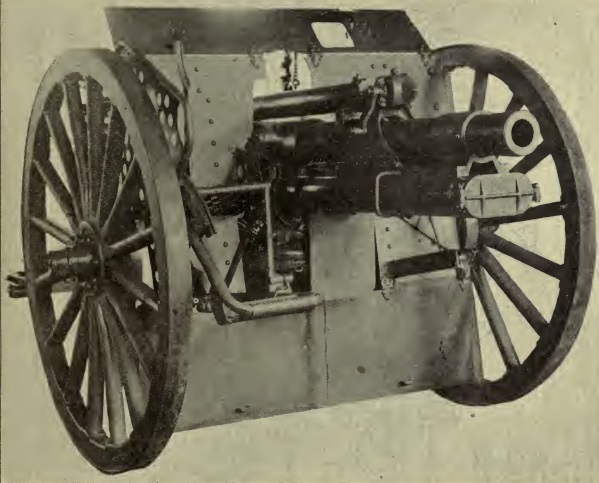
The US 3.2-Inch Gun Materiel M1897 was a modification of the M1890 field gun to enable it to use smokeless powder but it still used a fixed carriage without a recoil system. Unfortunately, it was very quickly rendered obsolete when the French adopted the rapid fire Canon de 75 Mle 1897 in the same year that incorporated the first effective long recoil system. Once the secrecy over the French gun had been lifted, the US quickly moved to develop a more modern gun that was designated the 3-Inch Gun Materiel M1902 using a hydro-spring recoil system.
The M1902 was very much a US first generation rapid fire gun and, before WW1 began, work had already started to develop a much better gun. The main limitations of the M1902 were considered to be the limited on-carriage traverse (8°), the limited maximum elevation (15°) and therefore maximum range of only 6,000 yds, the lack of an independent line of sight (the ability to lay the gun for direction and elevation independently) and the manually operated screw breech that limited the rate of fire. A new gun designated the 3-Inch Gun Materiel M1913 was therefore developed using a split trail based on the ideas of Colonel A Deport who had been responsible for the design of the Mle 1897. The new gun incorporated a semi-automatic drop block breech. It also divided the recoil system to position the hydraulic buffer above the gun with the recuperator below it to put the centre of gravity on the gun’s centreline and so minimise the ‘jump’ when the gun fired.
Following testing, modifications were made to the gun and it eventually entered service as the 3-Inch Gun Materiel M1916. However, the decision was taken to concentrate the limited spare US production capacity on the Mle 1897 or 75 mm Gun M1897 in US designation and therefore very few M1916’s reached France during WW1. Those that did had been modified to fire the same ammunition as the M1897 in which form it was designated the 75 mm Gun Materiel M1916.
In the inter-war period, with limited funding available, further light field gun developments were concentrated on improving the M1897 rather than the M1916 as there were very many more of the former in the inventory. It was also the case that the M1916 was by then not highly regarded with the complex design of the top carriage, elevating and traversing mechanisms in particular causing it to suffer after hard use resulting in accuracy problems with the gun . However, the limited number of M1916’s manufactured were eventually modified to include spring suspension and pneumatic tyres for high speed mechanised towing and some were supplied to the British Army after Dunkirk for training purposes. However, by the start of WW2, the US Army’s main light field gun was the 75 mm Field Gun M1897 on the M2 carriage.
Gun Design
The gun was of the built-up construction with a jacket shrunk on to the rear half of the tube. There were six slightly varying types of this gun but the variations dealt only with the jacket and locking hoop were attached and did not affect the general dimensions. The gun was guided in recoil by two flanges on the lower side of the jacket. A lug on top near the forward end of the jacket containing a T-slot held the forward end of the recoil cylinder. A short hoop or clip was shrunk on the tube near the muzzle and had on its underside two lugs which formed guides for the gun on the cradle.
The breech ring screwed into the rear end of the jacket and formed a housing for the breech block which slid up and down with the action of a wedge. The ring carried a top lug to which the hydraulic recoil cylinder was secured with a lug underneath to which the two spring piston rods were attached. The breech block was of the drop-block type and operated semi-automatically with the breech closing automatically when a round of ammunition was inserted. It was opened by pulling back the handle on
the right side of the breech which not only lowered the breech block but also operated the extractor ejecting any empty cartridge case. When a round was inserted smartly into the breech, its rim struck the lips of the extractor causing the mechanism to close under the action of the closing spring. The cartridge primer was fired from the left side of the carriage by a continuous pull firing
mechanism. The firing pin was cocked and fired by one continuous backward motion of the firing handle on the left side of the cradle.
Carriage Design
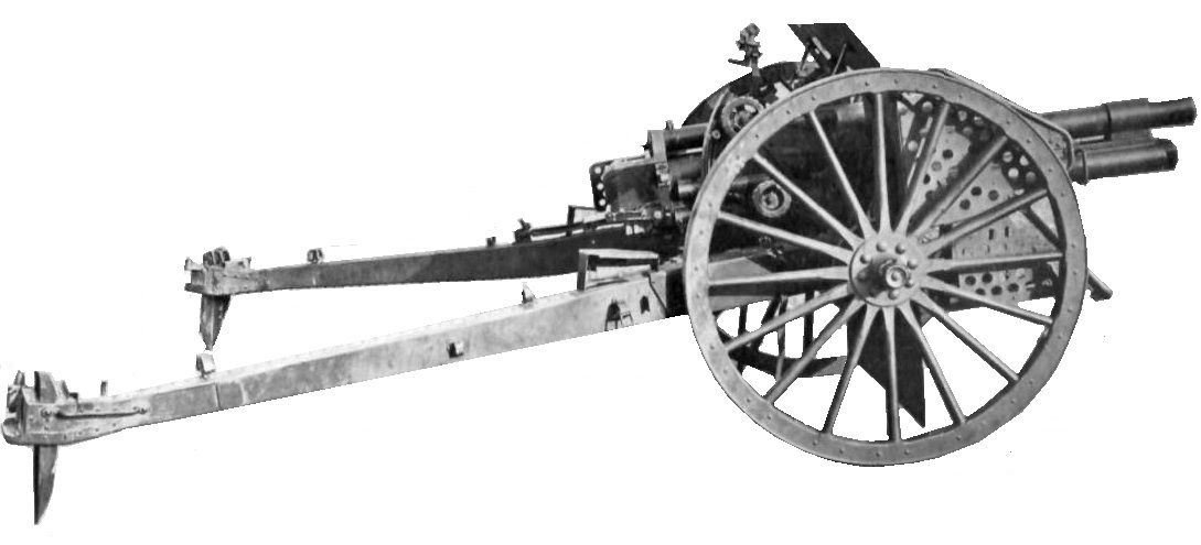
The M1916 used a split trail with the legs pivoting outwards on the bottom carriage behind the wheel axles. The so-called flasks that connected to the wheel axles were joined to the bottom carriage via a universal joint allowing one flask to be raised by up to 18° relative to the other to accommodate uneven ground. Spades were mounted at the ends of the trail legs via ratchets that allowed their height or depth to be adjusted.
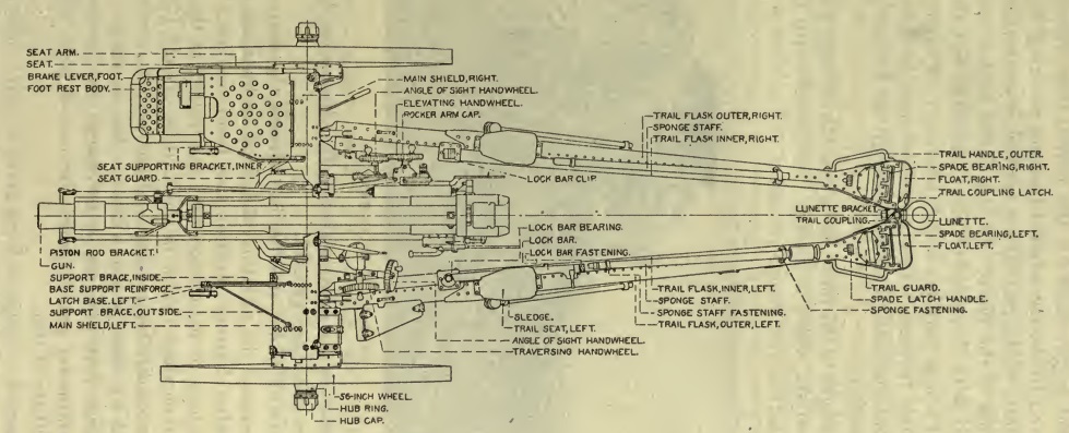
Two seats were mounted on the trail legs opposite the breech for the Gunner on the left and the No. 1 on the right.
The carriage was fitted with a full sized shield to protect the gun crew. The main part consisted of a left and right half with a space in between to allow the gun to elevate through. The two halves were mounted on the bottom carriage via brackets and stays, and braced by the full width hinged top shield. This had a hinged cover for the panoramic telescope viewing window. Below the main part of the shield was hinged apron with a small piece of shield fixed underneath the cradle to protect the top carriage and elevating mechanism.
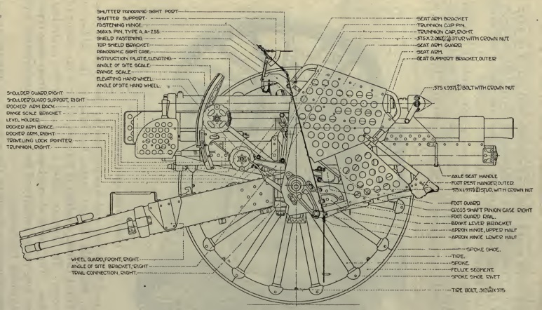
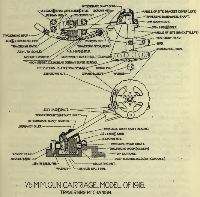
The top carriage was a complex set of castings that rotated in azimuth above the wheel axle on a pintle. The sides of the top carriage provided bearings for the cradle trunnions to allow the gun to be elevated. The left side of the top carriage housed a curved rack that was used to rotate the top carriage by 22.5° in azimuth in either direction about the pintle using a hand wheel as shown.
As with the British and French field guns used in WW1, the M1916 used a sighting system providing a so-called independent line of sight. In direct fire, this enabled the Gunner on the left of the breech to traverse the gun and set the angle of sight (AOS) on the target while the No. 1 on the right of the breech was independently able to set the tangent elevation of the gun to correspond to the required range.
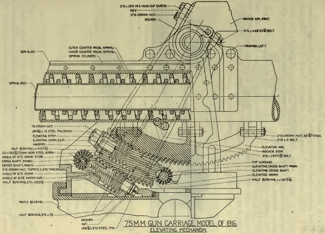
The independent line of sight was achieved as shown below using a so-called rocker made up of a U-shaped casting that passed under the cradle and pivoted on the trunnions above which were a left arm mounting the sights and a right arm mounting the elevating hand wheel. The elevating arc was fixed to the cradle and was rotated by a worm gear in a housing at the bottom of the rocker. The elevating hand wheel rotated a shaft via bevel gears that, in turn, rotated a cross-shaft at the bottom rear of the rocker that rotated the elevating worm via bevel gears. In this way, tangent elevation could be applied to the gun without moving the rocker and affecting the AOS providing a maximum of 7° of depression and 53° of tangent elevation.
The toothed bottom of the rocker meshed with an AOS worm mounted in a housing on the top carriage. The worm was rotated via bevel gears by a cross shaft at the front of the rocker that had hand wheels on both sides of the top carriage to be operated by either the Gunner or the No. 1. This mechanism provided an AOS range from -7° to 11°. Adjusting the AOS, applied this to the gun to which was added the tangent elevation to give it the final quadrant elevation.
Variants
The hydro-spring recoil system was found to degrade with hard combat use with the weakened springs failing to run the gun fully back after firing at higher angles of elevation. To solve this problem, a new hydro-pneumatic recoil mechanism was designed in 1917 at the French firm of FAMH (often referred to as St Chamond) by Col Rimailho who assisted in the design of the Mle 1897. The modified gun was designated the M1916MI. However, it is likely that very few M1916’s were modified in this way since, by then, WW1 had ended and funding was in short supply.
During the 1930’s, the both the M1916 and M1916MI versions of the gun were modified for high speed mechanised towing that included sprung axles and pneumatic tyres. The modified guns were designated the M1916A1b and M1916MIA1.
Transport
For towing, the trail legs were closed together and then the towing eye attached to a two wheeled limber to be pulled by 6 horses. The limber chest carried 18 rounds of ammunition.
![]()
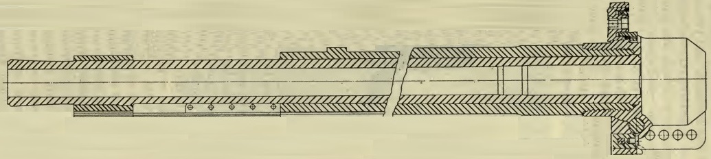
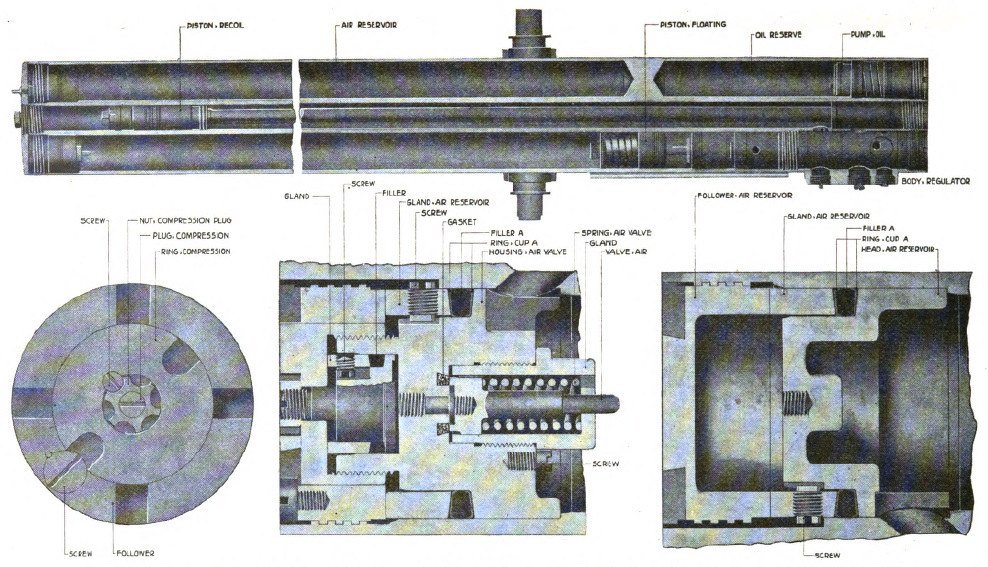
Recoil System
The M1916 hydro-spring recoil system was unusual because the spring recuperator responsible for returning the gun to battery was mounted underneath the gun while the hydraulic buffer was mounted above the gun. The reason for this was to position the centre-of-gravity of the recoil parts on the centreline of the gun to minimise the ‘jump’ on firing. In the Mle 1897 by way of contrast, as the gun fired, there was a tendency for it to naturally rotate upwards about the centre-of-gravity which was underneath the gun. This effect was called ‘jump’ and had to be taken into account when setting the required elevation of the gun.
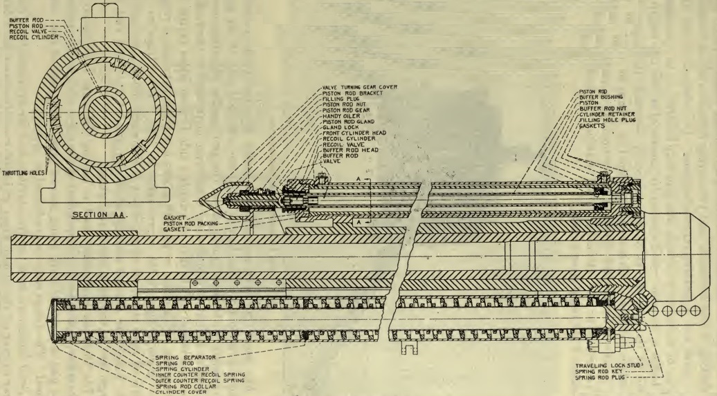
In the M1916, the design of the hydraulic buffer was complicated because it had to provide a variable recoil length that had to be shortened as the gun elevation (as in a howitzer) to stop the breech hitting the trail of the ground. The variable recoil system provided a recoil length of 46 inches at 0° elevation reducing to 18 inches at 53 elevation. This was achieved using an inner cylinder referred to as the recoil valve to which the piston was keyed. The buffer cylinder (and recoil valve inside it) were attached to a lug above the breech and therefore recoiled with the gun. The piston was fixed to the rear end of a hollow rod attached to the valve turning gear that was fixed to the cradle via a bracket. As the gun recoiled, the buffer cylinder was drawn backwards while the piston remained stationary.
The buffer cylinder was filled with oil and as the piston effectively moved forwards, the oil in front of the piston was forced through throttling holes in the recoil valve cylinder into the space behind the piston. The constriction in flow of the oil through the throttling holes produced the retarding force to absorb a considerable amount of the recoil energy. The variable recoil length was achieved using a control rod on the right-hand side of the cradle attached to a pivot near the right trunnion that was pulled backwards as the gun elevated. The front end of the rod was attached to an arm that rotated the valve turning gear that rotated the piston that, in turn, rotated the recoil valve cylinder since the piston was keyed to it. This rotation of the recoil valve as the gun elevated, reduced the number of throttling holes uncovered and, by increasing the constriction of the oil flow, also increased the retarding force during recoil reducing the length of recoil.
The recuperator was responsible for absorbing some of the recoil energy and, once the recoil ended, to use this stored energy to return the gun to battery. The recuperator consisted of a pair of cylinders machined from a single forging that also acted as the gun cradle. Within each cylinder was a rod attached to the lug underneath the breech with a collar attached at the front of the rod. Between the collar and the rear of each cylinder were inner and outer springs, each one in two parts with a separator disk in between. When the gun recoiled, the springs were compressed between the collar and the rear of each cylinder. After the recoil ended, the springs then pulled the gun back into battery. However, to provide a smooth stop to the counter-recoil, the piston rod was fitted with a buffer rod attached to the rear of the buffer cylinder. As the gun returned to battery, the buffer rod had to displace oil inside the piston rod past thereby dampening the motion.
The original hydro-spring recoil system gave problems in returning the gun to battery at the higher angles of elevation after hard use. The problem was caused by the variable recoil system that limited the recoil length to 18 inches at the highest elevation angle. This resulted in only a small amount of spring compression inside the recuperator and stored energy that was insufficient to return the gun to battery after the recoil had ended. To solve this problem, a hydro-pneumatic recoil mechanism was developed by Colonel Rimailho at the St. Chamond factory. The advantage of the hydro-pneumatic recoil mechanism was that it stored most of the recoil energy rather than dissipating it as heat and therefore retained enough energy to return the gun to battery at all elevation angles. The resulting carriage was designated the M1916MI.
The hydro-pneumatic recoil system was housed in a new cradle and the original hydraulic buffer and spring cylinders were discarded. The new recoil system was made up of 3 cylinders within the cradle. The middle one was filled with oil and contained a piston at the front of a piston rod that was fixed to the lug underneath the breech. The piston therefore recoiled with the gun.
As the gun recoiled, the piston in the middle cylinder forced the oil backwards through throttling ports in the regulator into the rear of the left-hand cylinder. This oil then pushed the floating piston forward to compress the air at the front of the left-hand cylinder. However, to give the required length of recoil, the front of the left-hand cylinder was connected to the front of the right-hand cylinder whose front two thirds formed an additional length of air cylinder. After the recoil had been brought to an end, the air pressure then pushed the gun back into battery.
The regulator and the valves it contained controlled both the recoil and the counter-recoil movements. It also contained a mechanism for providing a variable recoil length using a control rod on the left of the cradle. The length of recoil at 0° elevation was 46 inches reducing to 22 inches at 43° elevation.
Sights
The sighting on the M1916 provided for an independent line of sight that allowed a very high rate of fire in direct mode; in other words, when the target could be seen in the sights or, more specifically, the M6 panoramic telescope. In direct mode, the Gunner in the left-hand seat traversed the gun and changed the angle of-sight (AOS) to put the M6 sight on the target using the two hand wheels provided. The No. 1 in the right-hand seat then elevated the gun to give the required range. By splitting the task of laying the gun in direction and elevation sped up the sighting process.
Originally, the M1916 would have used an M1915 panoramic telescope. The M1915 had a magnifying power of 4 and a field of view of 10° and was provided with a fixed eyepiece at the bottom and a viewing head at the top that could be rotated through 360°. The azimuth scale provided was graduated into 64 equal divisions of 100 mils. The micrometer adjuster for it was graduated from 0 – 100 in 1 mil divisions. The M1915 was also provided with a deflection scale and micrometer with a dial on the rear face. The dial was graduated from 0 – 100 and numbered every 10 mils.
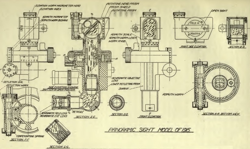
The panoramic telescope was slotted into a bracket at the top of the left-hand rocker arm. The sight mount was reciprocating or azimuth compensating in US terminology to compensate for the gun trunnions not being level, which was the norm. The tilt in the trunnions caused the vertical plane through the gun to be rotated in azimuth in the direction of the lowest trunnion. If not compensated, this led to a large sighting error especially at higher elevation angles. It was compensated by tilting the sight body sideways to put it back into the vertical plane using the cross level about a pivot that had to be maintained parallel to the gun – that way, the vertical planes through both the sight and the gun would then be parallel. The sight pivot was maintained parallel to the gun using a parallel motion link whose control rod was connected to an arm attached to the left-hand trunnion.
The elevating hand wheel used by the No. 1 on the right of the breech was mounted on the end of the right-hand rocker ar. A curved range dial was fixed to the right-hand side of the cradle allowing a pointer on the end of the rocker arm to indicate the range selected. In direct fire mode, the Gunner was responsible for traversing the gun and setting the AOS on to the target while the No. 1 set the required range on the range dial. In indirect fire mode, the Gunner centred his sight on an aiming point that could be a prominent feature on the landscape or specially set up aiming posts. The offset angle of the target from the aiming point was set on the panoramic telescope and then the gun was traversed until the sight was centred on the aiming point. However, before this was done, the No. 1 changed the AOS using his hand wheel to level the longitudinal level on the right rocker arm before elevating the gun to give the required range.
Ammunition
The 75 mm Gun Materiel M1916 was designed to  fire the same ammunition as the Mle 1897. At the beginning WW1, the Mle 1897 fired two main types of shells: a high explosive (HE) shell and a shrapnel shell. The muzzle velocity of the shrapnel shell was 1,693 fps achieving a maximum range of 9,650 yds. The muzzle velocity of the HE shell with short fuze was 1,900 fps achieving a maximum range of 12,360 yds.
The HE shell on the left weighed 5.3 kg or 12 lb and was thin walled and filled with a picric acid explosive called Melinite. The shell could be fitted with a variety of percussion fuzes: super-quick, delayed or graze. The HE shell shown is fitted with a French M1916 super quick fuze designed to explode the shell at ground level. The delay fuzes were designed to explode the shell after it had penetrated some distance into the ground while the graze fuze ensured the shell exploded at grazing angles to the ground.
The shrapnel shell weighed 7.24 kg or 16 lb and was filled with 290 lead/antimony balls. In US use, it used a M1915 or similar combination fuze (time and percussion fuze in British terminology) that provided a time delay of up to 21 s but also contained a percussion detonator to set off the shell in case it hit the ground first. When the time fuze had burned through, a central tube conducted the flash to a bursting charge at the base of the shell separated from the shrapnel balls by a steel disk. Detonation of the bursting charge then resulted in the front of the shell and the shrapnel balls being ejected at high speed to spray the ground ahead of the shell.
Later in WW1, various other types of shell were developed including for anti-aircraft use, to deliver smoke or gas and to provide illumination in the form of star shells.
75 mm Gun Materiel M1916 Specifications
- Length: 14 ft 3 in (with folded trail legs)
- Width of Track: 60 in
- Wheels: 56 in
- Weight of Gun & Carriage: 3,045 lb
- Length of Gun Barrel: 90.9 in (30.8 calibres)
- Length of Bore: 84 in
- Bore: 75 mm
- Weight of Gun & Breech: 749 lb
- Muzzle Velocity: 1,900 fps (HE Shell)
- Maximum Range: 12,360 yds
- Trail: Split trail
- Recoil System: hydro-spring (later hydro-pneumatic)
- Maximum Recoil: 18 – 46 inch
- Rifling: Polygroove with modified plain section
- Twist: RH 1:119 to 1:25.4 9.72 in from muzzle; then uniform
- Grooves: 24
- Firing Method: Percussion
- Elevation: -7° to +53°
- Traverse: 22.5° to left and right
![]()