

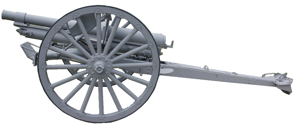
The US 3.2-Inch Gun Materiel M1897 was a modification of the M1890 field gun to enable it to use smokeless powder but it still used a fixed carriage without a recoil system. Unfortunately, it was very quickly rendered obsolete when the French adopted the rapid fire Canon de 75 Mle 1897 in the same year that incorporated the first effective long recoil system.
When the initial secrecy over the French gun was lifted, the US Ordnance Department quickly started work to produce a US rapid fire field piece. In 1897-98, Captain Charles B Wheeler designed a 3 inch gun and carriage using hydraulic cylinders to absorb the recoil, springs in the cylinders to return the tube to the firing position and a spade at the rear of the trail to check carriage recoil. However, this was a short recoil system and therefore did not prevent the gun from having to be re-laid after each round was fired. It also fired bagged cartridges like the M1897 rather than metallic cartridges again slowing down the achievable rate of fire.
Although the Ordnance Department was impressed with Wheeler’s gun, they believed a better field gun could be developed. Therefore, in 1901, guns were tested with both a short recoil system and a long recoil system and compared with the M1897 field gun. After the trials, the Department concluded that long recoil systems were superior as they were steadier under fire, recoiled without requiring frequent relaying, and fired six times faster than the M1897 gun. The Ordnance Department therefore ceased experimenting with the other systems in February 1902 and narrowed its choice to three long recoil systems: the Bethlehem No. 2, the Erhardt (a German gun), and the Ordnance Department’s model designed by Wheeler. The Department did not consider any of these guns completely satisfactory and so decided to create the new gun, designated the 3-Inch Gun Materiel M1902, by combining the best features of Wheeler’s design and the Erhardt gun.
The M1902 was very much a US first generation rapid fire gun and, before WW1 began, work had already started to develop a better gun with a greater maximum elevation and on-carriage traverse. This resulted in the experimental 3-Inch Gun Materiel M1913 that was then refined to become the 3-Inch Gun Materiel M1916. While the M1902 guns largely remained in the US to be used for training purposes during WW1, some M1916 guns found their way to France and were even modified to fire French 75 mm ammunition (75 mm Gun Materiel M1916). However, the American Expeditionary Force (AEF) mainly used the French Mle 1897 as US industry was not geared up to produce enough guns.
Gun Design
The gun was made of nickel steel and consisted of the tube and the jacket. The jacket was shrunk on to the rear half of the tube and was secured in place by a shoulder on the tube and a locking hoop shrunk over the front of the jacket. A hinge lug for the breech block carrier was machined on the right-hand side for the breech block and a lug was machined underneath the breech to connect the gun to the recoil system. On the lower part of the gun, extending the entire length of the jacket and locking hoop, were two recoil guides or clips which fitted over and secured the gun to the guide rails on the cradle. It was also fitted with a front guide or clip that was shrunk on to the tube closer to the muzzle. The gun cradle was horseshoe in shape with the upper edges flanged outwards and connected via a top plate that was riveted on. The flanges were bronze lined and formed the guides for the gun to recoil along.
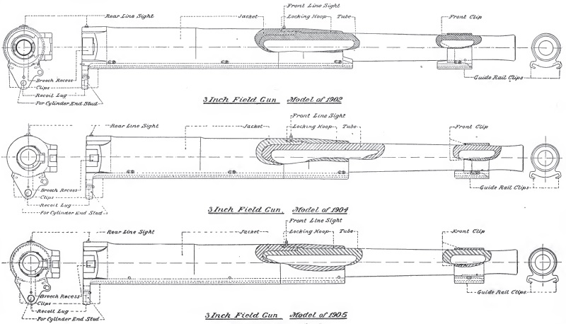
There were 3 variants of gun used: the M1902, the M1904 and the M1905. The breech block on all three models was of the interrupted screw type and rotated in the block carrier that was hinged to the rear end of the jacket on the right side. The block of the M1902 had two threaded and two slotted sectors but the identical blocks of the M1904 and M1905 had four threaded and four slotted sectors. The M1905 was basically a lightened version of the M1904 with a 47 lb weight saving.
The breech blocks were operated by a lever pivoted to a lug on the block carrier which had at its outer end a handle and, at its pivot end, a segment of a bevel gear meshing with a corresponding segment on the rear face of the block. On pulling the handle to the right, the first 117° rotated the block until the threaded sectors were disengaged. A further movement of 90° then swung the block and carrier on its hinge until the block was free of the bore. When the breech was opened, an extractor automatically ejected any cartridge in the breech. Pulling the operating handle to the left closed the breech and then locked it in position ready for firing the next cartridge.

In the M1902 gun, closing the breech automatically cocked the firing mechanism. However, in the M1904 & M1905 guns, a so-called continuous pull trigger mechanism was used that did not have to be separately cocked. All the models were fired either using a lanyard attached to the trigger or via the firing handle on the right side of the carriage that operated the trigger via the firing handle shaft and trigger arm.
Carriage Design
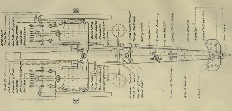
The trail consisted of two steel C-beams with the flanges turned inward and tied together by transoms and plates. At the front end of each beam was a forged steel axle bearing that was split so it could be slipped over and secured to the axle by clamping bolts. Near to the forward end and rivetted to the beams were the front and rear elevating gear transoms. Behind these were the front and rear toolbox transoms with a bottom plate in between to form a tool box enclosed by a hinged lid secured by a spring handle catch. The portion of the trail between the rear end of the tool box and the wheel guard transom was a box formed for the transportation of the rear sight shank. The portion of the trail to the rear of the sight box was closed by a top plate that was riveted on. The beams at the points of contact with the limber wheels when making short turns were protected by small plates called wheel guards strengthened by the wheel guard transom.

The rear of the trail was fitted with a spade with a float plate above it to prevent the spade from digging in too far. Lifting handles were provided on either side of the float plate and a socket was provided in the centre for the handspike used to traverse the end of the trail when necessary.
The carriage was fitted with 2 round seats on either side adjacent to the breech for use by the two gunners. The carriage was also provided with 2 front axle seats with tubular guards in front of the shield for use during transporting of the gun. The footrests for the seats were each supported on the end of two 4 inch diameter longitudinal tubes each housing a round of ammunition that were accessed behind the shield via a hinged door.
The wheels were fitted with cast iron brake shoes that pivoted on arms inside the brake beam tubes fixed to the front ends of the ammunition tubes. The inner ends of the brake arms were operated via rods connected to a brake lever mounted behind the shield and operated by the right-hand gunner.
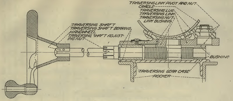
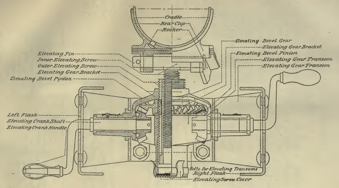
The gun cradle was mounted on the rocker that formed a platform on which it elevated and also traversed. The front of the rocker was fitted with a socket to take the pintle underneath the cradle that allowed it to traverse 4° to the left and right. The pintle socket was also equipped with two bronze lined holes through which the wheel axle fitted to allow the rocker and cradle to rotate in elevation. The rear of the rocker was fitted with a housing for the traversing gear that was operated via a hand wheel on the left-hand side that rotated a screw with a nut fixed to the cradle.
The elevating gear was mounted on transoms between the trail beams and operated a vertical double screw via bevel gears with the top of the inner screw connected to a swivel pin on the end of the rocker. The trail was fitted with elevating handles on both sides of the gun that rotated the elevating screws via bevel gears. The use of two elevating handles allowed for both one-man and two-man laying. The gun could be depressed by up to 5° and elevated by up to 15°.
Transport
The gun was towed by 6 horses behind a two wheel limber. The limber carried an ammunition chest that contained 36 rounds and other small stores.
![]()
Recoil System
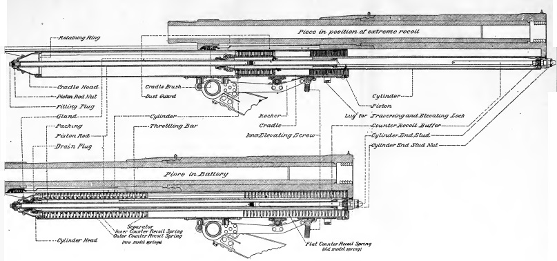
The recoil system consisted of a hydraulic cylinder within the cradle containing a piston on the rear end of a rod connected via a nut to the front of the cradle. The rear end of the hydraulic cylinder was bolted to the lug under the breech and therefore recoiled with the gun.
Although the interior of the hydraulic cylinder was cylindrical, 3 longitudinal ribs or throttling bars of uniform width but varying height extended from the rear of the cylinder to within 19 inches of the front. Notches in the piston for the ribs formed ports for the passage of oil with the varying height of the ribs ensuring a constant retarding force during recoil. The total length of recoil was 45 inches.
Around the outside of the hydraulic cylinder were 3 separate spring sections sandwiched between a flange on the front of the cylinder and the rear of the cradle. As the gun recoiled, these springs were compressed absorbing some of the energy of recoil. When the recoil ended, the springs then pushed the hydraulic cylinder and gun back into battery. In order to bring to gun to a gentle stop, the back of the hydraulic cylinder contained a control rod that entered the hollow rear section of the piston rod towards the end of run out. The hollow piston rod was filled with oil that the control rod had to displace.
Sights
The M1902 was fitted with the following instrument for sighting and laying the gun: line sights, a rear and front sight, a panoramic telescope sight and a range quadrant. The line sights consisted of a simple post on the front of the jacket and a fixed V-notch on the rear. The line sights were only intended for rough laying of the gun for direction.
The front and rear sights were for general use in direct laying. The front sight took the form of a set of cross hairs mounted on the top of a bracket that fitted into a socket on the left side of the cradle in front of the shield. The rear peep sight was mounted on the rear sight assembly that also included the panoramic telescope sight as shown below.
The rear sight assembly was mounted on a bracket that fitted into a socket on the left side of the cradle. Attached to the bracket was a shank socket in which the toothed shank (or arc) could be raised or lowered using the scroll gear handle on the right. The rear of the shank was graduated in yards up to 6,500 in divisions of 50 yds. The rear peep sight was mounted on a deflection screw providing up to 45 mils (2.5°) of deflection to the left or right. When the sights were set for a particular range, it was then only necessary to elevate the gun until the elevation level was levelled.
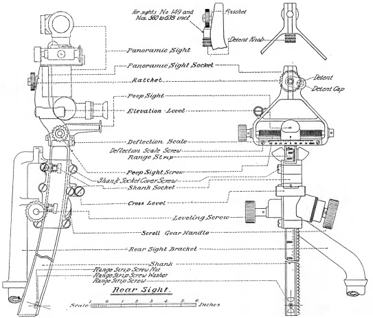
The M1902 sights were reciprocating or azimuth compensating in US terminology to compensate for the effects of the carriage wheels not being level, which was the norm. The tilt of the wheels caused the vertical plane through the gun to be rotated in azimuth in the direction of the lowest wheel and, if uncompensated, resulted in a large sighting error. To compensate for the wheel tilt, the shank socket could be tilted sideways on the sight bracket using the levelling screw with a cross-level provided to indicate when the sights were back in the vertical plane.
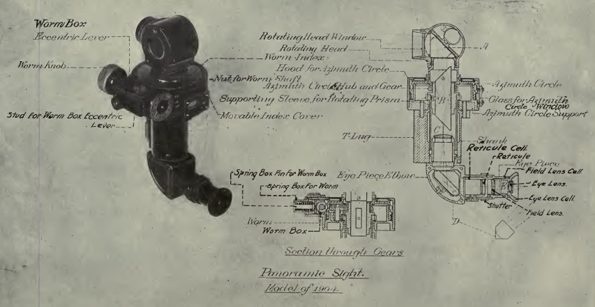
The M1902 was originally fitted with an M1904 panoramic sight mounted in a socket on top of the shank although, later on, this was replaced by an M1915. The M1904/M1915 were used for indirect fire and were provided with a fixed eyepiece at the bottom and a viewing head at the top that could be rotated through 360°. The azimuth scale provided was graduated into 64 equal divisions of 100 mils. The micrometer adjuster was graduated from 0 – 100 in 1 mil divisions. The M1915 panoramic telescope was similar to the M1904 but was also provided with another micrometer to allow the elevation angle for the sighting head to be adjusted.
In indirect fire, the target direction was specified as an offset angle from an aiming point that could be a prominent feature on the landscape or could be aiming posts specially planted for the purpose. The aiming point could be in front of the gun, to the side or behind it. Once the relative target direct was set on the sight, it was only necessary to then traverse the gun until the aiming point was centred in the sight.
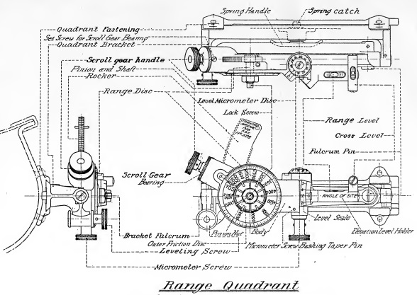
In principle, the Gunner in the left-hand seat could lay the gun for both elevation and direction using the rear site assembly. However, it was decided that much fast laying could be achieved by getting the Gunner in the right-hand seat to lay for elevation using the range quadrant mounted on a bracket on the right side of the cradle. The quadrant itself pivoted at the front and could be raised or lowered at the back via the rocker toothed arc using the scroll gear handle. A range disk was provided driven by the rocker that was graduated up to 6,500 yds in 50 yd intervals. The quadrant also pivoted sideways about a bracket fulcrum that was parallel to the gun and, using the cross level and screw, needed to be tilted into the vertical plane. The elevation level on the front of the sight was provided with an angle of sight adjustment with a scale graduated from 0 – 6 in 100 mils intervals (3 being horizontal) with the micrometer graduated from 0 – 100 in 1 mil intervals. In practice, the angle of sight was set on the sight followed by the required range and then the gun was elevated until the elevation level was levelled.
Ammunition
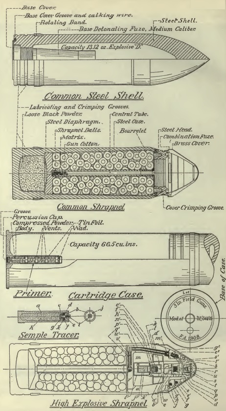
The M1902 fired fixed ammunition (projectile and cartridge fixed and loaded together) with the metal cartridge cases incorporating a percussion primer in the base. The powder was a nitrocellulose powder composed of multi-perforated (7 perforations) cylindrical grains, each 0.35 inch long and 0.195 inch in diameter. The charge varied slightly for different lots of powder but was approximately 24 ounces. For the shrapnel shells, the powder charge was designed to give a muzzle velocity of 1,700 fps. For the other types of shell, the charge was varied to produce a muzzle velocity that gave a similar range versus elevation angle performance.
The gun fired 3 types of projectile: common steel shells, shrapnel shells and high explosive (HE) shrapnel shells.
The common steel shell had a 2 calibre radius head (CRH) and contained a bursting charge of 13.12 ounces of Explosive D. The weight of the shell with bursting charge and fuze was 15 pounds. It was fitted with a percussion fuze in the base.
The common shrapnel shell weighed 15 lb and contained 252 metal balls. When the time fuze in the nose ignited, the flash passed down the central tube to ignite a bursting charge of 2.75 oz of black powder in the base. This blew off the front of the shell and ejected the shrapnel balls out of the front to provide an anti-personnel function.
The M1902 also fired HE shrapnel shells designed by Erhardt and were based on the German concept of a universal shell. The shell was filled with 285 metal balls and contained a bursting charge of 2 oz of black powder. When the time function of the fuze ignited, the flash passed down the central tube to set off the bursting charge as in the common shrapnel shell. However, the shrapnel balls with encased in HE. The HE could not be set off by the igniferous time fuze but, if this function was disabled or the shell hit the ground before the time fuze was ignited, a percussion function in the combination fuze detonated the fuze and this then detonated the HE surrounding the shrapnel balls. Although the HE shrapnel shell was considered useful at the time, as with the German universal shells, it proved not to be effective in combat use and was later dropped in favour of separate HE and shrapnel shells.
3-Inch Gun M1902 Specifications
- Length: 13 ft 9 in
- Width of Track: 60 in
- Wheels: 56 in
- Weight of Gun & Carriage: 2,520 lb
- Length of Gun Barrel: 87.8 in (29.2 calibres).
- Length of Bore: 84 in
- Bore: 3.0 in (76 mm)
- Weight of Gun & Breech: 835 lb for M1902 & M1904; 788 lb for M1905
- Muzzle Velocity: 1,700 fps
- Maximum Range: 8,500 yds (6,000 yds at 15° elevation)
- Trail: Single pole
- Recoil System: hydro-spring
- Maximum Recoil: 45 inch
- Rifling: Polygroove with modified plain section
- Length of Rifling: 72.72 in
- Twist: RH
- M1902 & M1904 Twist: 1:50 to 1:25 cal 12.52 in from muzzle; then uniform
- M1905 Twist: 0 to 1:25 cal 9.72 in from muzzle; then uniform
- Grooves: 24
- Firing Method: Percussion
- Elevation: -5° to +15°
- Traverse: 4° to left and right
![]()