

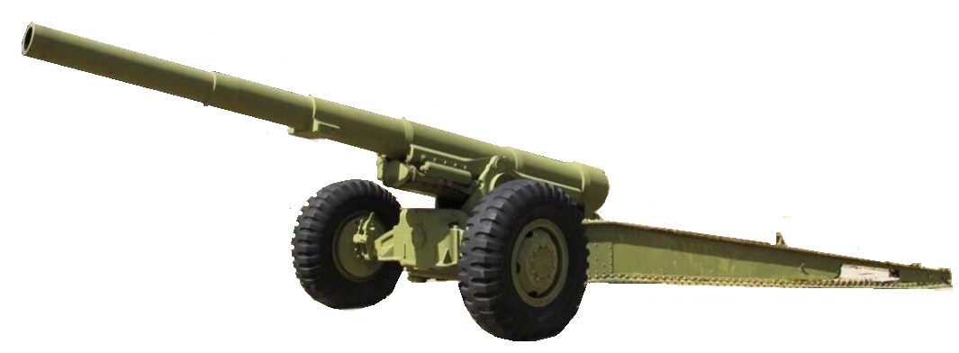
The Canon de 155 Mle 1917 GPF (Grande Puissance or great power Filloux) was designed during WW1 by Colonel Louis Filloux while working at the state arsenal at Puteaux (Atelier de Construction de Puteaux) in order to provide the French Army with a long range heavy field gun. The gun was 33 calibre long and produced a muzzle velocity of 2,411 fps with a 115 mm shell weighing 43.2 kg / 95 lb giving a maximum range of 17,700 yds.
The US army had not developed their own heavy field gun for use during WW1 and therefore adopted both British and French weapons as a result. This included the British 8 inch and 9.2 inch howitzers, the French 155 mm Mle 1917 Schneider and the 155 mm Mle 1917 GPF, the latter as a long range heavy field gun.
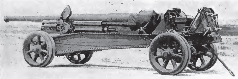
The French manufactured GPF guns in US service were designated the 155 mm Gun Materiel M1917. However, when the gun was subsequently manufactured in the US, it was then designated as the 155 mm Gun Materiel M1918. It should be noted that the US followed the French approach of using the word ‘materiel’ to describe a complete artillery piece. The original M1917 & M1918 were designed for slow speed transport and used wheels with solid rubber tyres on the carriage. For later higher speed transport, the carriage was then modified with improved brakes and wheels fitted with pneumatic tyres.
The M1918 remained in service until the end of WW2. However, following WW1, the Westervelt Board was convened to review the use of artillery during the war and to make recommendations regarding future artillery requirements. Although the M1918 was considered to be adequate as the main heavy field gun in the interim, it recommended the development of a new carriage for the gun to provide 0° – 65° of elevation and a range in excess of 25,000 yds. This eventually resulted in the 155 mm Gun M1 ‘Long Tom’ adopted in 1938.
Gun Design
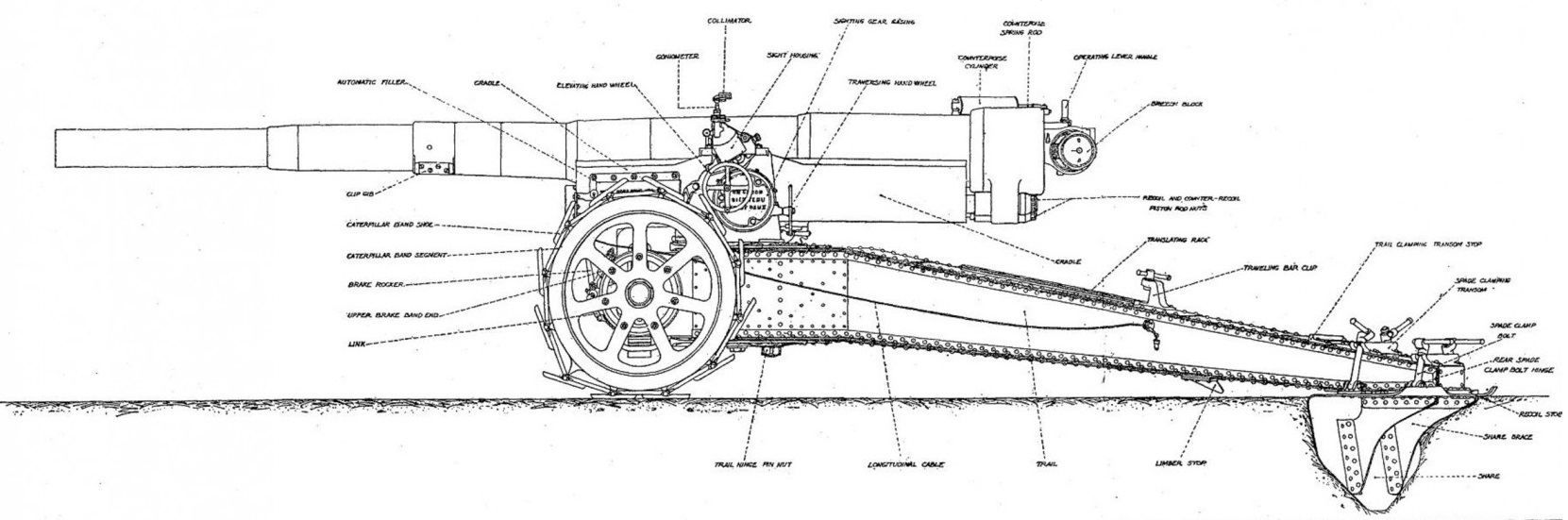
The M1917 & M1918 guns were 232.87 inches or 38 calibres in length and of built up construction. The jacket was made up of four separate sections which were shrunk on to the rifled tube extending 3/4 of the way to the muzzle. The breech ring was screwed on to the rear of the jacket and included a lug underneath to attach the gun to the recoil system. The gun was fitted with rectangular bronze runners fixed to the jacket that allowed the gun to recoil within guides on either side of the cradle.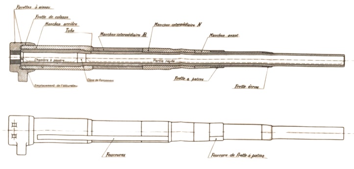
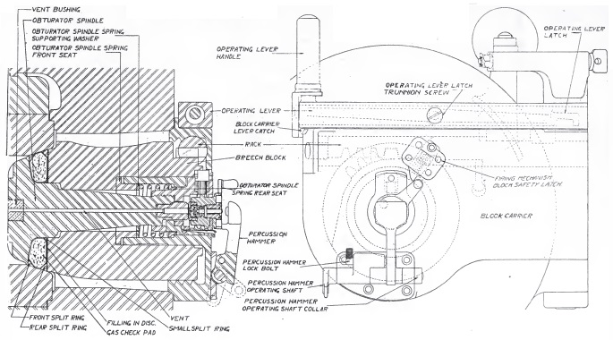
The M1917 & M1918 guns fired bagged cartridges and was fitted with an interrupted thread breech. A single motion operating lever was used and, when pulled back and to the right, rotated the breech plug to allow it to be withdrawn past the interrupted threads and then swung to the right-hand side of the breech ring. In order to support the weight of the breech when it was opened and closed with the gun was elevated, a spring strut was mounted on top of the breech ring that connected to the breech carrier.
Obturation or sealing of the breech was accomplished by a mushroom shaped obturator in the centre of the breech plug with a sealing ring behind its head. When the breech was closed, the sealing ring was pressed against the tapered end of the combustion chamber. When the round was fired, the combustion chamber pressure forced the obturator backwards inside the breech plug compressing the sealing ring and forcing it harder against the chamber sides to seal the breech. The bagged charges were igniting using a percussion cartridge or primer (as the us called them) inserted into the back of the breech whose flash travelled down a central vent in the breech plug. The hammer to fire the percussion cartridge via a firing pin was operated via a lanyard at the back of the breech.
Variants
In producing the US M1918 variant of the artillery piece, a modified breech was introduced resulting in the M1918MI model of the gun. In this model, the breech block carrier was modified and a new firing mechanism was installed. The original M1917 gun was modified in the same way to produce the M1917A1 model.
Carriage
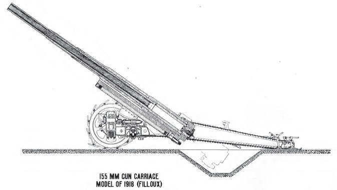
The M1917 & M1918 carriage was of split trail design with spades at the end of each leg to help steady the gun during firing. The trail legs pivoted on the side wings of the bottom carriage. The bottom carriage provided a transverse chamber at the front for the wheel axle that pivoted sideways on a pin to accommodate uneven ground. In the original carriage, the axle was supported on leaf springs when being transported but was lowered on to the axle using jacks to put it into the firing position. The axle mounted wheels were fitted with a pair of rubber tyres suitable for mechanised towing. They could also be fitted with Cingoli which were articulated plates that increased the contact area of the wheels on the ground making it easier to support the weight of the gun on soft ground. The carriage was equipped with hand operated drum brakes on each wheel.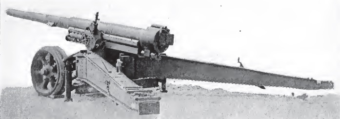
The gun recoiled on guides on either side of the cradle that consisted of a steel casting containing the recoil system. It was fitted with trunnions on either side for mounting on the top carriage to allow the gun to be elevated to 35°. The top carriage in turn was mounted on the bottom carriage on a horizontal bearing that allowed the gun to be traversed by up to 30° in either direction.
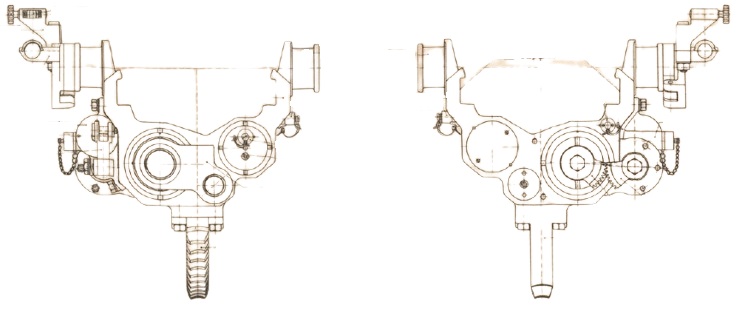
The top carriage shown below was provided with a hand wheel at the rear to traverse the gun that operated a worm gear at the bottom front via a gear train that engaged with a toothed arc on the bottom carriage. The hand wheel on the left-hand side of the top carriage operated a large worm gear running fore-aft via a gear train that engaged with the elevating arc under the gun cradle.
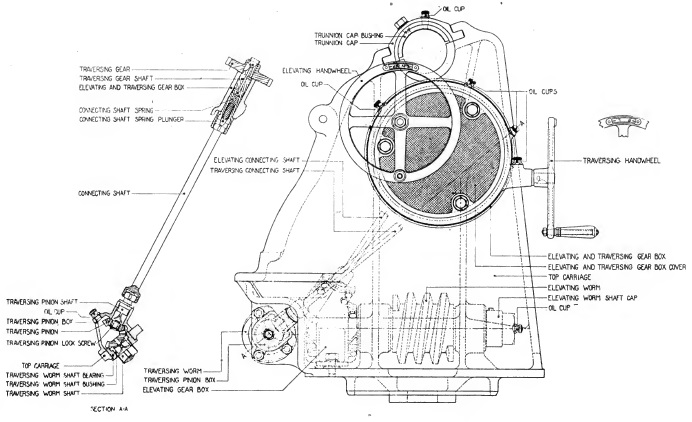
The worm gear and toothed arcs for both the traversing and elevating mechanism can be seen in the drawing below.
For mechanised towing, a limber with a pair of steerable wheels and a towing bar was attached to the rear of the trail. In order to prepare for transporting, the gun was unbolted from the recoil mechanism and slid backwards on the trail and then clamped in position to even the weight distribution between the two pairs of wheels. Both pairs of wheels were provided with sprung suspension to make towing at a higher speed possible.
Variants
The M1917 & M1918 used 6 variants of the original carriage. The M1918 carriage was identical to the original GPF carriage but simply manufactured in the US. The A1 variant of both carriages were modified for higher speed transport by equipping them with anti-friction roller bearings for the wheels and electric brakes operated by the towing vehicle. The M2 & M3 variants were modified for high speed transport and were equipped with wheels with 24 x 14 inch pneumatic tyres and air brakes. The original semi-elliptic springs on which the gun axle was suspended in the travelling position was also eliminated in these models.
Recoil System
The M1917 & M1918 incorporated a hydro-pneumatic recoil system accommodated in the cradle and consisted of 3 separate cylinders. The hydraulic buffer was on the left looking forwards; the smaller recuperator liquid cylinder was in the middle and the recuperator high pressure (HP) cylinder was above on the right. In US parlance, counter-recoil was the equivalent of the British term recuperator.
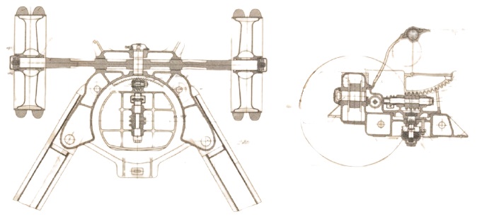
The hydraulic buffer consisted of an oil filled cylinder housing a piston on the end of a hollow rod that was bolted to the lug on the breech ring so that, when the gun was fired, the cylinder remained stationary and the piston was drawn backwards. Inside the hollow piston rod was an inner control rod with grooves cut into its surface. The piston in turn was fitted with ports that allowed the oil to seep past it during recoil via the grooves in the inner rod providing enough constriction to absorb a lot of the energy of recoil.
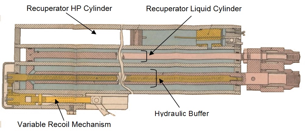
The recuperator was responsible for absorbing some of the energy of recoil and then using this energy to return the gun to battery after the recoil had ended. The recuperator was made up of two cylinders. The liquid cylinder was filled with oil with a piston fitted on the end of a rod connected to the breech lug. The HP cylinder was filled with high pressure nitrogen gas in front of a floating piston with oil behind it. As the gun recoiled, the piston in the liquid cylinder forced the oil behind it into the back of the HP cylinder. The oil forced out of the liquid cylinder pushed against the floating piston in the HP cylinder which, in turn, compressed the nitrogen in front of it. This absorbed some of the gun’s recoil energy and, once the recoil had been brought to an end, the nitrogen pressure then forced the floating piston backwards which, in turn, forced oil back into the liquid cylinder. This forced its piston forward at the same time returning the gun to battery. The ambient nitrogen pressure in the HP cylinder had to be maintained at about 600 psi to keep the gun fully run out at all elevation angles.
As with many higher elevating field pieces, it was necessary to restrict the length of recoil of the M1917 & M1918 as the gun elevated to prevent the breech hitting the ground. This was accomplished by rotating the inner piston rod as the gun elevated which had the effect of reducing the contact area between the grooves and the piston ports increasing the braking effect. The mechanism for doing this can be seen in the drawing below at the bottom left. The mechanism was adjustable to give the order of about 70 inches of recoil at 10° of elevation and about 43 inches at 28°. Although the length of recoil was reduced as the gun was elevated, it was still necessary to dig a pit under the breech in order to provide enough clearance during recoil.
Sights
The M1917 & M1918 were designed so that one man operated the sights and both elevated and traversed the gun using the hand wheels provided. They were fitted with a US designed M1918 quadrant sight mounting an M6 panoramic telescope. The sights were reciprocating to allow them to compensate for the wheels and trunnions not being level, which was the norm. Trunnion tilt caused the vertical plane through the gun to be rotated in azimuth in the direction of the lowest trunnion and, if uncompensated, would lead to a large sighting error especially at higher angles of incidence.
The M1918 quadrant sight was mounted on the left trunnion and therefore elevated with the gun. It was provided with a mechanism on the front that allowed the sights to be tilted sideways about an axis that remained parallel to the gun. By using the cross-levelling knob and cross level, the sights could be adjusted to put them into a vertical plane that was then parallel to that of the gun compensating for any tilt in the gun trunnions. However, this adjustment had to be done each time the elevation of the gun was changed.
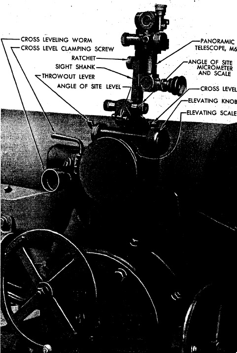
The tangent elevation was set on the elevation drum using the throw out lever and elevating knob. The elevation drum was graduated from 0 – 800 mils (0° – 45°); setting a tangent elevation angle on the sight, tilted the sights forwards by that angle. The sight mount also incorporated a sight clinometer or angle of sight level (as the US called it) that allowed the angle of sight to be set. It was graduated in 100 mil intervals numbered from 0 to 6 with setting 3 corresponding the the clinometer being level. The micrometer was graduated from 0 – 100 in 1 mil intervals. In practice, the quadrant elevation set on the gun was the sum of the angle of sight and the tangent elevation settings. Once set on the sight, the gun was then elevated until the clinometer bubble was level. The quadrant elevation could also be set or checked using a gunner’s quadrant place on a flat on top of the breech.
The M1917 & M1918 were mainly used for indirect fire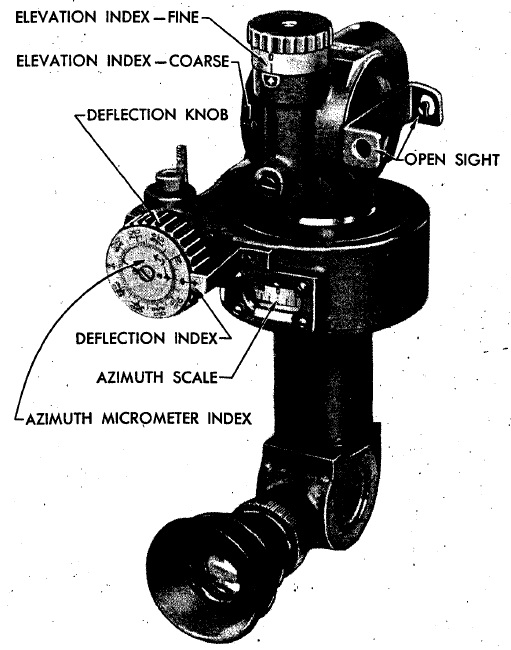 using the M6 panoramic telescope in laying for direction. This was a four power telescope with a fixed eyepiece at the bottom and a viewing head at the top that could be rotated through 360°. The azimuth scale provided was graduated in 100 mil intervals from 0 – 32 mils (0° – 180°) in either direction with the micrometer graduated from 0 -100 in 1 mil intervals. The telescope was also provided with an elevation adjustment for the angle of sight.
In indirect fire, the target direction was specified in terms of an offset bearing from an aiming point defined for the gun which could be a prominent feature in the landscape or specially set up aiming posts that could be in front of the gun, behind the gun or to one side. To aim the gun at the target required the offset bearing to be set on the sight and then the gun traversed until the aiming point was centred in the sight.
Ammunition
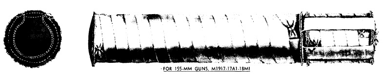
The M1917 & M1918 used bagged cartridges that could be made up from a base section 6″ in diameter and 28.5″ long to produce the normal charge of 20 lb of smokeless powder, or an increment section 8.5″ long could be added to produce a supercharge of 26 lb of smokeless powder for use at extreme ranges. An igniter consisting of 8 oz of black powder was sewn into the base charge that was ignited by a percussion primer inserted into the back of the breech.
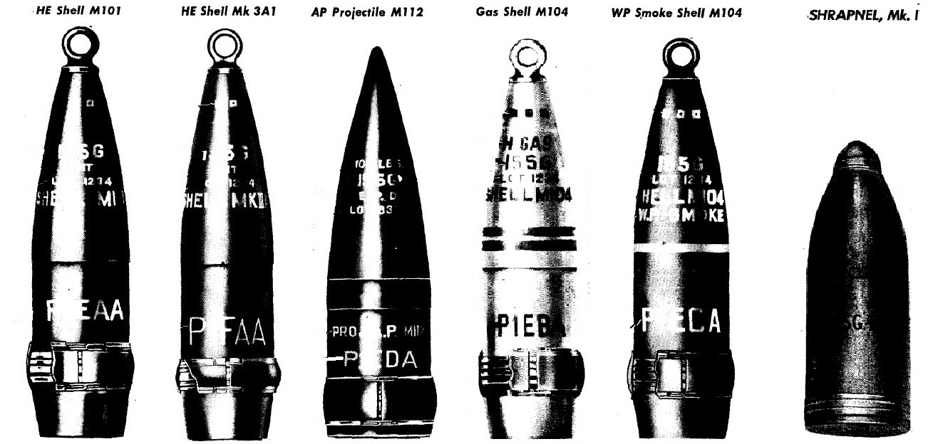
The M1917 & M1918 originally used French designed shells characterised by having 2 narrow driving bans with the later shells having a single wider driving band. By WW2, 5 different types of shell were fired by the M1917 & M1918: high explosive (HE), armour piecing (AP), gas, smoke and shrapnel. These were used with super-quick and delay fuzes M51, M46 & M47 together with the time & percussion M1907 fuze providing up to a time delay of 45 seconds.
The older Mk III HE weighed 95 lb, was 25.54″ long and was filled with up to 15 lb of TNT or Amatol. The newer M101 HE shell weighed 95 lb, was 26.79″ long and was filled with a bursting charge of up to 16 lb of TNT or Amatol. The M112 AP shell weighed 108 lb, was 23.62″ long and contained a bursting charge of 1.44 lb of Explosive D. It was fitted with a windshield to provide armour penetration. The M104 gas shell was of similar size and weight to the HE shell and contained a chemical filling of 11.7 lb together with a small bursting charge. The M104 smoke shell weighed 99 lb, was 26.82″ long and contained a phosphorous filling of 16.9 lb together with a small bursting charge. The Mk I shrapnel shell was 18.83″ long and contained 800 shrapnel balls together with a bursting charge of 1.21 lb. All the shells except for the AP and shrapnel shells had a 11 calibre radius head and were boat tailed.
155 mm Gun Materiel M1918 Specifications
- Length: 27 ft 11 in
- Maximum Width: 105 in
- Wheels: 24 inch metal rims with 14 inch pneumatic tyres
- Weight of Gun & Carriage: 23,275 lb
- Weight of Gun: 8,715 lb
- Length of Gun: 232.87 in or 38 calibres
- Bore: 155 mm
- Muzzle Velocity: 2,411 fps
- Maximum Range: 17,700 yds
- Trail: Split box trail
- Recoil System: Hydro-pneumatic
- Maximum Recoil: 70 inches at 10° elevation and 43 inches at 28°
- Rifling: Uniform 1 turn in 29.9 calibres
- Length of Rifling: 185 in
- Twist: Right-hand
- Grooves: 48
- Firing Method: Percussion
- Elevation: 0° to +35°
- Traverse: -30° left to +30° right
![]()