

The US army had not developed satisfactory field guns for use during WW1 and therefore adopted both British and French weapons as a result. These included the British 18-Pdr & French Canon de 75 Mle 1897 field guns, the French 155 mm Mle 1917 Schneider and 155 mm Mle 1917 GPF medium field guns, and the British 8 inch and 9.2 inch heavy howitzers.
Following WW1, the Westervelt Board was convened in the US to review the use of artillery during the war and to make recommendations regarding future artillery requirements. Neither the US nor France had made use of light field howitzers during WW1 but it was noted that both the British and Germans had used them effectively in the form of the 4.5-Inch QF Howitzer and the 10.5 cm leichte Feldhaubitze 16, respectively. The board concluded that the light field gun they proposed required a light field howitzer to accompany it. They therefore recommended the development of a 105 mm howitzer to provide 0° – 65° of elevation and a range in excess of 12,000 yds
Development began in 1920 with many lessons learned from looking at the design of the German light howitzers even to the extent of adopting the same calibre. This resulted in the horse drawn 105 mm Howitzer M1 that was standardised in 1928 although funding constraints meant that it was never put into production. When mechanisation of the Army began shortly afterwards, it became necessary to modernise all the horse drawn equipment. Although some work was started on the M1, financial issues put the work on hold and it was not until 1936 that it resumed. However, by then, it was decided that it would be better to start again with a fresh design and this eventually resulted in the 105 mm Howitzer M2 being developed and standardised in 1940.
The 105 mm Howitzer M2 served throughout WW2. In 1962, its designation changed to the M101 Howitzer and, in this form, it saw service in both the Korean War (1950-53) and the Vietnam War (1955-75). Although no longer used by the US Army, it is still in service elsewhere in the world.
Gun Design
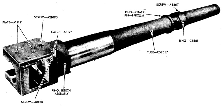
The 105 mm gun M2 was forged from a single piece of steel with a length of 101.35 inches or 24.5 calibres and was subjected to autofrettage. This manufacturing process resulted in residual compressive stresses being imparted to the gun barrel in a similar way to that found in built-up or wire wound guns that then resisted the internal pressure of firing. The bore was rifled for most of its length with the chamber for the propellant charge machined into the rear part.
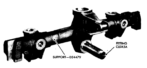
The gun was supported in the recoil sleigh shown below on which it recoiled on the cradle. It was clamped to the front yoke of the recoil sleigh between a flange machined on the gun barrel and a screw-on locking ring at the front. The breech was fitted with two lugs underneath that slotted into corresponding notches in the recoil sleigh rear yoke to stop the barrel rotating.
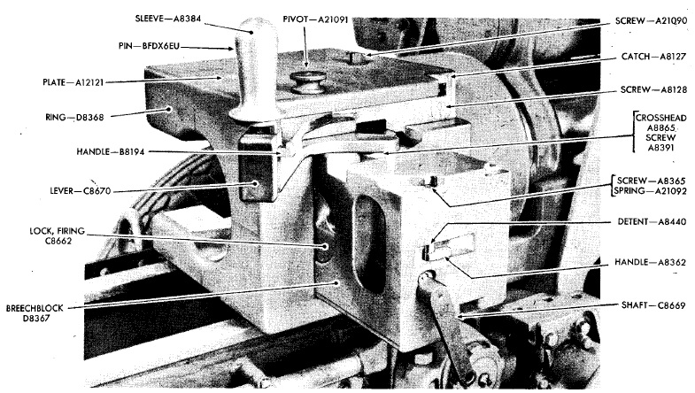
The gun fired semi-fixed ammunition and was fitted with a horizontal sliding block breech. The breech was opened to the right by pulling back on the operating lever which also caused the extractor to eject any cartridge case in the breech. The gun was fired using a lanyard that pulled back on the trigger shaft that was free to move backwards on the side of the trail against spring pressure. The shoe on the end of the trigger shaft in turn pulled back the trigger arm on the side of the breech that compressed the internal firing pin spring and then released the pin via its sear to set off any metallic cartridge in the breech. However, the trigger arm was only engaged by the trigger shaft shoe when the breech was fully closed providing an important safety feature.
Carriage Design
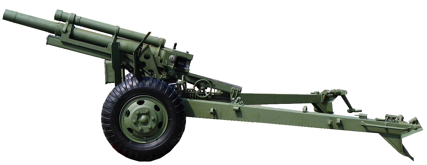
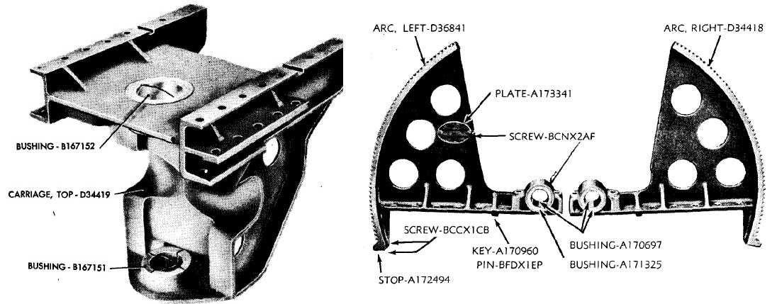
The 105 mm Howitzer M2 used a split trail with spades fixed to the rear of each leg. A handspike was fitted to the end of one leg and a drawbar for towing was fitted to the other. The bottom carriage consisted of the front support shown below with vertical bearings on either side to which the trail legs were attached. Stops were provided to limit the outward movement of each leg to 30°.
 The gun and recoil sleigh were mounted on the U-shaped cradle that contained trunnions to allow the gun to be elevated on the top carriage. The top carriage fitted on to the central vertical bearing on the bottom carriage and was held in place by a large pintle inserted from above. The pivot allowed the top carriage to be traversed by up to 23° to the left and right. The elevating arcs were bolted down on to the top carriage on either side and also provided the bearings at the rear for the cradle trunnions.
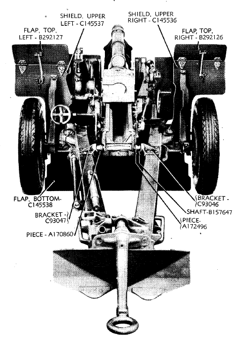
The wheels were mounted on the end of a girder axle that pivoted on a horizontal pin at the front of the bottom carriage. This allowed the wheel axle to tilt sideways to accommodate uneven ground in the firing position and essentially provide a 3-point support for the carriage. The wheels were fitted with drum brakes and each was provided with a hand brake lever on the front of the bottom carriage. A shield was fitted to protect the cannoneers with the main parts of the shield fixed to the bottom carriage including hinged flaps at both the top and bottom. The main shield incorporated a wide gap in the middle to allow the gun to be traversed. To provide complete protection, a central shield was mounted in front of the main shield attached to the top carriage.
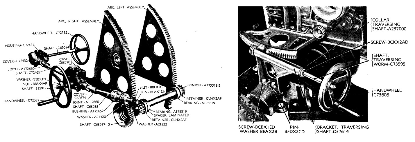
The gun was traversed by means of a worm driven by the traversing hand wheel that meshed with a curved horizontal rack bolted to the left-hand side of the top carriage. The gun was elevated by means of the two elevating arc bolted down on either side to the top carriage. A housing was fixed beneath the cradle that supported a cross-shaft with pinions either side that meshed with the front of the elevating arcs. The shaft was fitted with a worm wheel on the right-hand end driven by a worm on the end of a flexible shaft rotated via bevel gears by the right-hand elevating had wheel. This drive shaft continued backwards along the cradle to a cross-shaft inside another cradle housing that was rotated by another set of bevel gears. On the opposite end of the cross-shaft was a left-hand elevating hand wheel.
The cradle trunnions were positioned just below the breech producing a large preponderance of weight towards the muzzle. To balance this preponderance, the carriage was fitted with a spring equilibrator. The cradle was extended well behind the breech so that the recoil sleigh was fully supported for the full length of the recoil. The equilibrator was attached via a pivot between the rear of the cradle and the rear of the bottom carriage support as shown below. When the gun was lowered, this compressed the two co-axial springs in the equilibrator thus balancing the weight.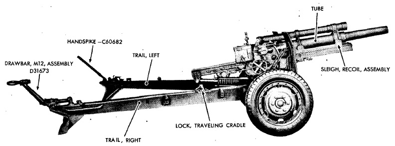
Recoil System
The hydro-pneumatic recoil system was mounted along with the gun on the sleigh shown below that recoiled on guides on either side at the top of the cradle. Unlike the recoil systems in most other artillery guns that used a separate hydraulic buffer and recuperator, the recoil system on the 105 mm howitzer M2 used a combined hydraulic buffer and recuperator. The buffer cylinder was mounted in the sleigh beneath the gun inside the cradle while the recuperator cylinder was mounted above the gun.
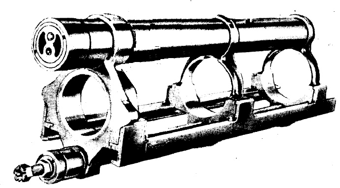
The hydraulic buffer (recoil cylinder in US terminology) was filled with oil and contained a piston on the end of a rod that was fixed by a nut on the closed front end of the cradle. The buffer cylinder was connected through a oil passageway in the front yoke of the recoil sleigh to the recuperator cylinder (counter-recoil cylinder in US terminology).
As the gun recoiled and the sleigh was pulled backwards, the oil in the buffer was forced by its piston into the front of the recuperator cylinder. Within the recuperator cylinder, the oil was then forced through one-way valves in the fixed regulator body where it pushed the diaphragm backwards that, in turn, pushed the floating piston backwards via the oil reserve that filled the space in between them. The movement of the floating piston then compressed the nitrogen gas at the rear of the recuperator cylinder. The gun’s recoil was partly absorbed by the constriction of the oil flow through the regulator body and partly by compressing the nitrogen gas.

A tapered control rod was fixed to the rear of the diaphragm that projected through a hole in the fixed throttling ring and also the centre of the regulator body. As the gun recoiled, the gap in the throttling ring and the forward tapered control rod gradually reduced until a point was reached were the oil flow was cut off completely and the recoil was brought to an end.
At this point the compressed nitrogen gas then forced the recuperator floating piston and diaphragm forwards. However, at this point, the one-way valves in the regulator body closed and the oil then had to flow past the control rod through the hole in the centre of the regulator body. However, the regulator body was fitted with a tube on the front side through which the oil had to flow to reach the front of the recuperator cylinder. Towards the end of the movement to fully run out the gun, the tight fitting un-tapered end of the control rod entered the control tube. Initially, oil was allowed to flow past via grooves cut in the walls of the control tube but these narrowed in the final stages of run out to bring the gun to a gentle controlled stop. This was aided by the one-way respirator valve at the front of the buffer cylinder which opened to let air in during recoil but closed and restricted the air escape during run out to provide an additional buffer.
Sights
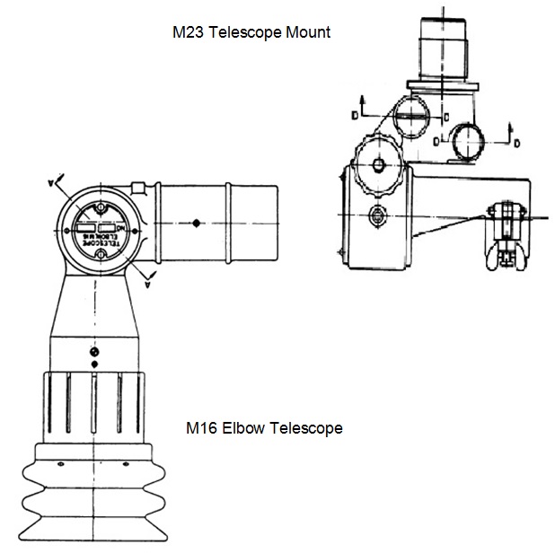
The M1 carriage used two-man laying for indirect fire. This meant that the Gunner on the left of the breech layed only for direction using an M12 panoramic telescope while the No. 1 on the right of the breech layed for elevation using an M4 range quadrant. However, for direct fire, the No. 1 made use of an M16 elbow telescope on an M23 telescope mounted on the range quadrant.
The panoramic telescope fitted into a socket on the M18 telescope mount and was offset by 45°for ease of use. The telescope mount consisted of 4 main parts: the mounting bracket, the rocker that provided longitudinal levelling, the sight body that provided cross-levelling, and the mounting socket for the panoramic telescope.
The mounting bracket was bolted to the cradle and the left-hand trunnion and therefore elevated with the gun. As a result, it was necessary to level the sight longitudinally after a change in elevation of the gun. The rocker contained a transverse bearing that allowed the sight body and cross-levelling mechanism to be rotated in the elevation plane using the levelling knob at the front of the rocker. The sights were adjusted to be in the vertical transverse plane using the longitudinal level.
The sights were reciprocating (azimuth compensating in US terminology) to allow them to compensate for the gun trunnions not being level, which was the norm. The result of trunnion tilt was to rotate the vertical plane through the gun barrel in azimuth in the direction of the lowest trunnion. If uncompensated, this would lead to a large sighting error that increased in magnitude as the gun was elevated. The effect was compensated for by tilting the sight body sideways about the cross-levelling pivot that was inside the body. The pivot was supported on the end of a shaft or arm whose inner end was fixed to the sight mounting bracket and was set up to be permanently parallel to the gun axis. The adjustment was carried out using the cross-levelling knob and the cross-level bubble.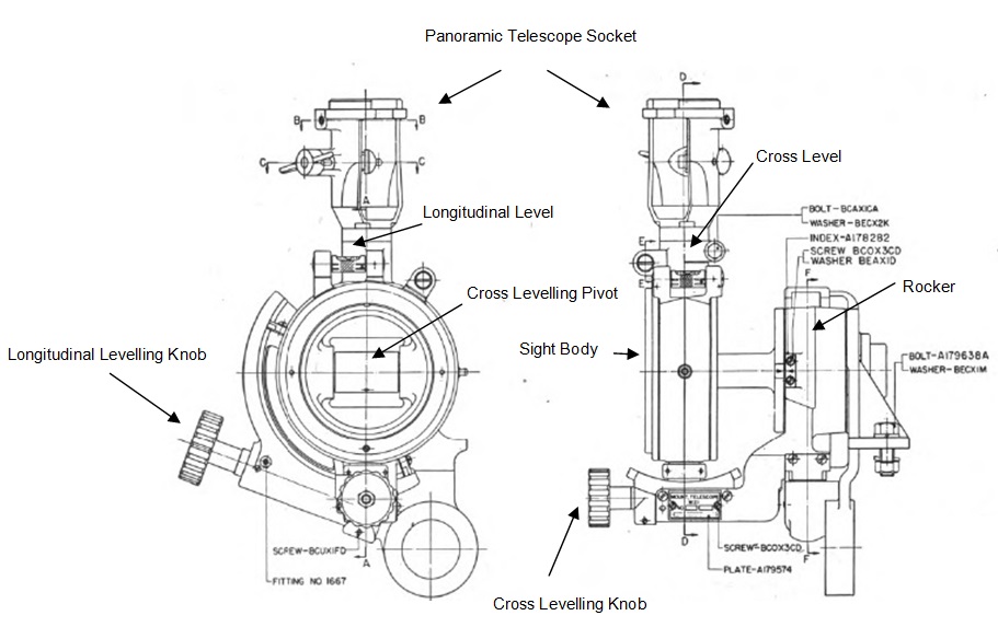
The M12 panoramic telescope provided  4 x magnification and a field of view of 10°. It used a fixed eyepiece at the bottom but with a sighting head at the top that could be rotated through 360° (6400 mils) using the quick release lever or the azimuth micrometer with an azimuth scale provided on the body. The scale was graduated in 100 mil intervals numbered 0 – 32 in both directions. The graduations on the azimuth micrometer were from 0 – 100 miles in 1 mil intervals. The telescope also included a separate micrometer knob to provide a deflection adjustment to account for drift or wind effects. The sighting head itself was provided with an elevation adjustment knob.
In indirect fire mode, the target direction was specified relative to an aiming point that could be a prominent feature in the landscape or aiming posts specifically set up for the purpose. The aiming point could be in front of the gun, to the side or behind it. In practice, the target relative bearing was set up on the panoramic telescope and then the gun traversed until the aiming point was centred in the sight. At that point, the gun was aligned with the target direction.
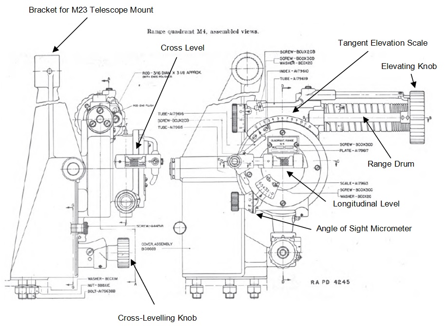
The range quadrant M4 was bolted to the cradle above and slightly ahead of the right trunnion. The main parts of the quadrant were the cross-levelling mechanism, the elevation mechanism, the angle of sight mechanism, and the illuminating system. In the same way as for the M21 telescope mount, the range quadrant M4 was provided with a cross-levelling mechanism and cross-level bubble to compensate for trunnion tilt.
The elevating gear was supported by a set of ball bearings mounted in a cylindrical portion of the body and was rotated by the elevating knob above it. A tangent elevation angle scale was provided graduated from 0 – 12 in units of 100 mils (0° – 67.5°). A micrometer was provided graduated from 0 -100 mils in units of 1 mil. The elevating gear carried the angle of sight mechanism, the angle of sight level and the cross level. The angle of sight scale was graduated from 0 – 6 in units of 100 mils with a setting of 3 corresponding to the horizontal. The adjustment micrometer was graduated from 0 – 100 in units of 1 mil.
In use, the angle of sight and the tangent elevation were set on the sight and then the gun was elevated until the longitudinal bubble was levelled. In addition to setting the tangent elevation on the site, a number of range drums were provided to be rotated by the elevating knob corresponding to different charge zones. The M4 range quadrant was provided with a battery powered illumination system for the elevation scale, angle of sight scale, micrometres, range drum and levels for night operation.
The M4 range quadrant could be fitted with the M23 telescope mount shown below along with the M16 elbow telescope for use in direct fire. The M23 telescope bracket screwed into the mounting hole at the top of the M4 range quadrant. The elbow telescope slid into the M23 body and was clamped in position using the clamping bolt. The telescope support bracket could be rotated by a screw adjuster and worm in the elevation plane to align the telescope with the gun axis. The support bracket was also provided with a bracket rotating worm and knob that allowed the telescope to be rotated about its objective axis. The M16 elbow telescope had a reticule fitted with 9 range lines representing elevations for ranges in 200 yd steps from 0 to 1,600 yds.
Howitzer Squad
The howitzer squad consisted of 8 cannoneers as follows:
Gunner: Set the azimuth deflection on the panoramic telescope and layed for direction.
No. 1: Set the angle of sight and range (elevation) on the range quadrant, opened and closed the breech, and fired the piece.
No. 2: Loaded the ammunition.
No. 3: Operated the fuze setter.
No. 4: Assisted No. 3 in setting fuzes and passing the rounds to No. 2 for loading.
No. 5: Assisted by Nos. 6 and 7, prepared charges and passed the assembled rounds of ammunition to No. 4.
Nos. 6 and 7: Removed ammunition from the containers and assisted No. 5 in preparing charges and assembling rounds. No. 7 kept empty cartridge cases out of the way of the gun crew.
Ammunition
 Except for the high explosive (HE) anti-tank (AT) round that uses a fixed propelling charge, the 105 mm Howitzer M2 fired semi-fixed ammunition. This consisted of a brass cartridge case that could be filled with different charges with muzzle velocities (MV) to suit different range zones but was mated with the shell before the complete round was loaded into the breech. The propellant used was Flashless Non Hydroscopic (FNH). There were 7 different charges:
- Charge 1: MV of 650 fps and maximum range of 3,825 yds.
- Charge 2: MV of 710 fps and maximum range of 4,475 yds.
- Charge 3: MV of 780 fps and maximum range of 5,280 yds.
- Charge 4: MV of 875 fps and maximum range of 6,430 yds.
- Charge 5: MV of 1,020 fps and maximum range of 8,295 yds.
- Charge 6: MV of 1,235 fps and maximum range of 10,150 yds.
- Charge 7: MV of 1,550 fps and maximum range of 12,205 yds.
The howitzer fired 4 types of shell: high explosive, smoke, gas and AT. The M1 HE shell weighed 42.07 lb complete, was 19.63″ long with fuze fitted, had a 6.02 calibre radius head (CRH) and was boat tailed. It was filled with 4.8 lb of either with TNT or with 50/50 Amatol. It was set off using a nose mounted Point Detonating (PD) M48 Superquick (SQ) or 0.15 s Delay Fuze or a Time Superquick (TSQ) M54 Fuze with SQ or Time Delay of up to 25 s.
The M60 shell was used to provide both smoke and gas payloads with a length of 19.46″, a 6.02 CRH and was boat tailed. With FS smoke, the shell weighed 34.82 lb with a 4.61 lb filling. With white phosphorous (WP) smoke, the shell weighed 34.31 lb with a 4.1 lb filling. With H Gas, the shell weighed 33.38 lb with a 3.17 lb filling of mustard gas in liquid form. They were set off with a PD M57 Fuze with SQ action.
The M67 HE anti-tank shell had a length of 19.43″, weighed 29.22 lb with a bursting charge of 2.93 of Pentolite. It was set off with a base detonating (BD) M62 Fuze with non-delay action. The shell contained a shaped charge of HE and was fitted with a ballistic cap that provided sufficient stand-off from the target before the fuze detonated. It could be used to penetrate up to 4″ of armour.
105 mm Howitzer M2A2 Specifications
-
- Length when Travelling: 19 ft 8 inches
- Maximum Width: 84.5 in
- Wheels: 20 inch wheels with 9 inch pneumatic tyres
- Weight of Gun & Carriage: 4,980 lb (in firing position)
- Length of Gun Barrel: 101.35 inch (24.5 cal)
- Bore: 105 mm
- Weight of Gun & Breech: 1,064
- Muzzle Velocity: 1,550 fps (HE shell)
- Maximum Range: 12,205 yds (HE shell)
- Trail: Split trail
- Recoil System: Hydro-pneumatic
- Maximum Recoil: 42 inches
- Rifling: Polygroove with plain section
- Twist: Right-hand 1 turn in 20 calibres
- Grooves: 34
- Firing Method: Percussion
- Elevation: -4.7° to +66.4°
- Traverse: -23° left to +23° right
![]()